Final Installation
In-Ceiling
After all cabling is complete, (if not previously done) connect the enclosure’s safety cord clip to the tab in the camera mechanism to allow the mechanism to hang from the enclosure. Align the 2 slots on the camera mechanism with the tabs in the enclosure, being sure to match up the arrows on both the drive and in the enclosure. Insert the camera mechanism into the enclosure until it snaps into place. Refer to Figure 9.
Note: Assure that there is no extra slack in the cabling that will interfere with proper installation and operation. Push any extra cabling up into the ceiling.
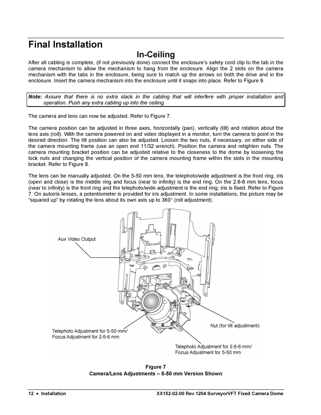
The camera and lens can now be adjusted. Refer to Figure 7.
The camera position can be adjusted in three axes, horizontally (pan), vertically (tilt) and rotation about the lens axis (roll). With the camera powered on and video displayed in a monitor, turn the camera to point in the desired direction. The tilt position can also be adjusted. Loosen the two nuts, if necessary, on either side of the camera mounting frame (use an open end 11/32 wrench). Position the camera and retighten nuts. The camera mounting bracket position can be adjusted relative to the closeness to the dome by loosening the lock nuts and changing the vertical position of the camera mounting frame within the slots in the mounting bracket. Refer to Figure 8.
The lens can be manually adjusted. On the
7.On autoiris lenses, a potentiometer is provided for iris adjustment. In some installations, the picture may be “squared up” by rotating the lens about its own axis up to 360° (roll adjustment).
Figure 7
Camera/Lens Adjustments – 5-50 mm Version Shown
12 • Installation |