1 |
|
| |
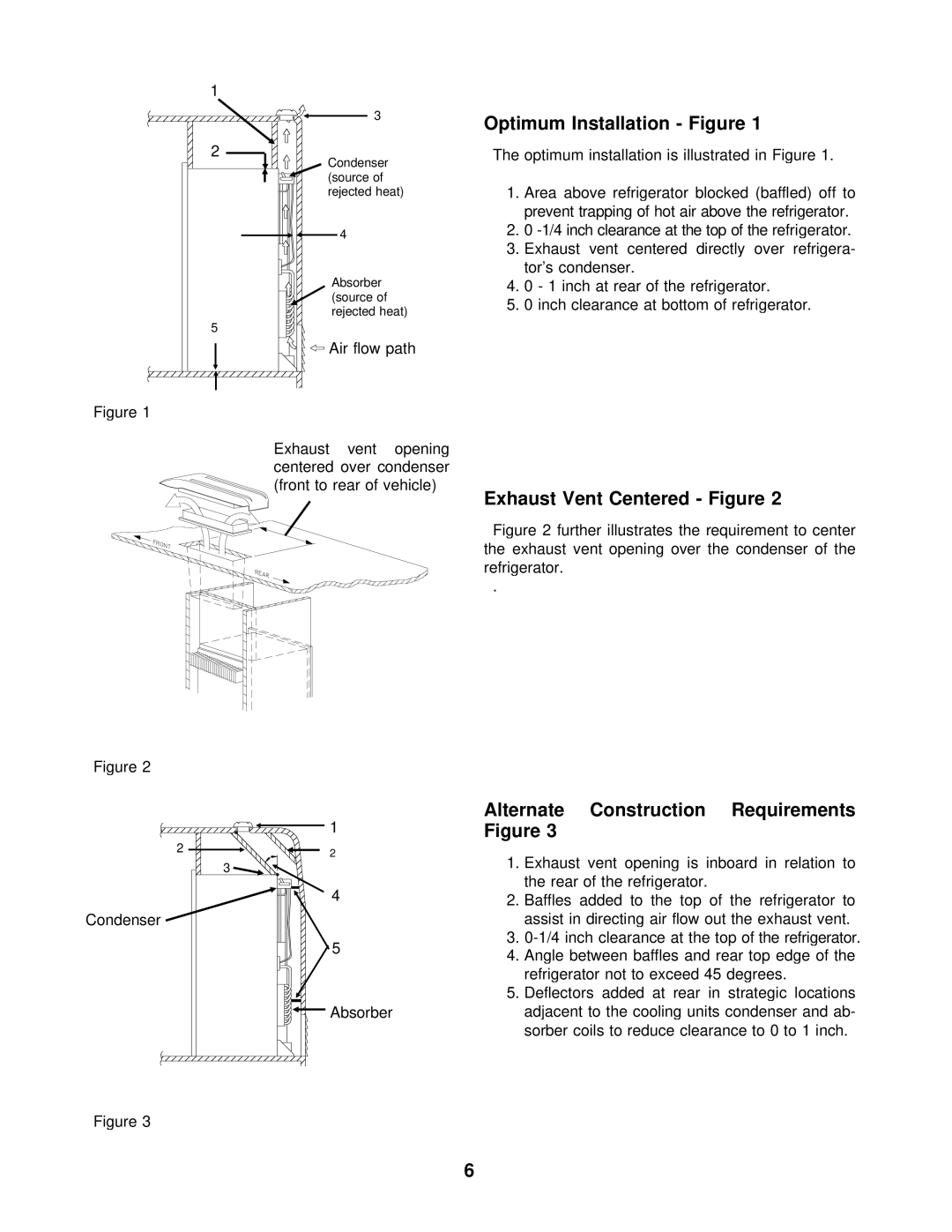
3 | Optimum Installation - Figure 1 | ||
| |||
2 | The optimum installation is illustrated in Figure 1. | ||
Condenser |
|
| |
(source of | 1. | Area above refrigerator blocked (baffled) off to | |
rejected heat) | |||
|
| prevent trapping of hot air above the refrigerator. | |
4 | 2. | 0 | |
| 3. | Exhaust vent centered directly over refrigera- | |
Absorber |
| tor’s condenser. | |
4. | 0 - 1 inch at rear of the refrigerator. | ||
(source of | 5. | 0 inch clearance at bottom of refrigerator. | |
rejected heat) | |||
|
| ||
5 |
|
| |
Air flow path |
|
| |
Figure 1
Exhaust vent opening centered over condenser (front to rear of vehicle)
Figure 2
| 1 |
2 | 2 |
| |
| 3 |
| 4 |
Condenser |
|
| 5 |
| Absorber |
Figure 3
Exhaust Vent Centered - Figure 2
Figure 2 further illustrates the requirement to center the exhaust vent opening over the condenser of the refrigerator.
.
Alternate Construction Requirements Figure 3
1.Exhaust vent opening is inboard in relation to the rear of the refrigerator.
2.Baffles added to the top of the refrigerator to assist in directing air flow out the exhaust vent.
3.
4.Angle between baffles and rear top edge of the refrigerator not to exceed 45 degrees.
5.Deflectors added at rear in strategic locations adjacent to the cooling units condenser and ab- sorber coils to reduce clearance to 0 to 1 inch.
6