LED | Color | On | Flash | Off | |
|
|
|
|
|
|
|
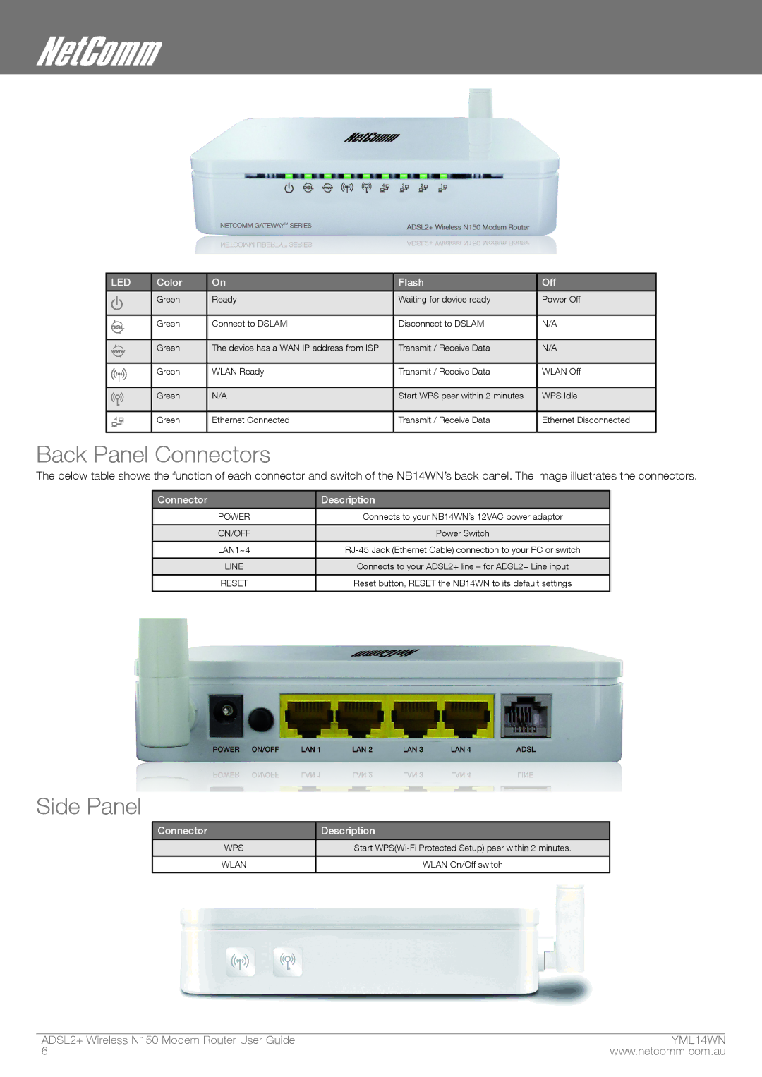
| Green | Ready | Waiting for device ready | Power Off |
|
|
|
|
|
|
|
| Green | Connect to DSLAM | Disconnect to DSLAM | N/A |
|
|
|
|
|
|
|
| Green | The device has a WAN IP address from ISP | Transmit / Receive Data | N/A |
|
|
|
|
|
|
|
| Green | WLAN Ready | Transmit / Receive Data | WLAN Off |
|
|
|
|
|
|
|
|
|
|
|
|
|
| Green | N/A | Start WPS peer within 2 minutes | WPS Idle |
|
|
|
|
|
|
|
| Green | Ethernet Connected | Transmit / Receive Data | Ethernet Disconnected |
|
|
|
|
|
|
Back Panel Connectors
The below table shows the function of each connector and switch of the NB14WN’s back panel. The image illustrates the connectors.
Connector | Description |
|
|
POWER | Connects to your NB14WN’s 12VAC power adaptor |
|
|
ON/OFF | Power Switch |
|
|
LAN1~4 | |
|
|
LINE | Connects to your ADSL2+ line – for ADSL2+ Line input |
|
|
RESET | Reset button, RESET the NB14WN to its default settings |
|
|
Side Panel
Connector | Description |
|
|
WPS | Start |
|
|
WLAN | WLAN On/Off switch |
|
|
ADSL2+ Wireless N150 Modem Router User Guide | YML14WN |
6 | www.netcomm.com.au |