E3 specifications
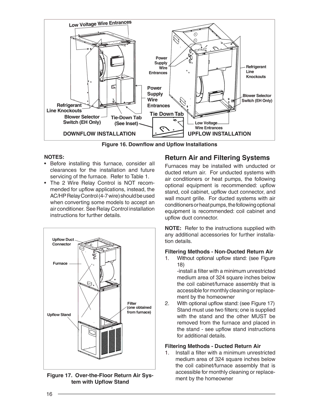
The Nordyne E3 is an innovative and efficient heating and cooling system designed to meet the demands of modern residential and commercial spaces. With a focus on energy efficiency and advanced technology, the E3 series offers a variety of features tailored to provide optimal comfort throughout the year.One of the standout characteristics of the Nordyne E3 is its multi-stage heating and cooling capability. This system utilizes a two-stage compressor, which allows it to operate at different capacities based on the current temperature demand. By adjusting its output, the E3 can maintain a more consistent indoor climate while maximizing energy savings. This not only enhances comfort but also reduces energy bills over time.
The E3 series also includes a variable-speed blower motor, which significantly improves airflow management. This technology enables the system to operate quietly and efficiently, reducing energy consumption while providing precise temperature control. Homeowners can enjoy a comfortable environment without the disruptive noise often associated with traditional HVAC systems.
Another key feature of the Nordyne E3 is its advanced refrigerant technology. The system uses R-410A refrigerant, an environmentally friendly option that has a lower impact on ozone depletion compared to older refrigerants. This commitment to sustainability aligns with the growing demand for eco-friendly solutions in the HVAC industry.
Additionally, the Nordyne E3 incorporates integrated Wi-Fi connectivity, allowing users to control their system remotely via smartphone or tablet. This smart technology enables homeowners to adjust temperature settings, monitor energy usage, and schedule maintenance alerts from virtually anywhere.
Energy Star certification further highlights the E3’s commitment to energy efficiency. Systems bearing this label are rigorously tested to ensure they meet strict guidelines for energy consumption, providing peace of mind for consumers looking to reduce their carbon footprint.
In summary, the Nordyne E3 heating and cooling system stands out for its energy-efficient design, advanced technologies, and commitment to comfort. With features like multi-stage operation, variable-speed motors, eco-friendly refrigerants, and smart home compatibility, it represents a significant step forward in HVAC technology. Homeowners can rely on the E3 to create a comfortable living environment while also contributing to a more sustainable future.

