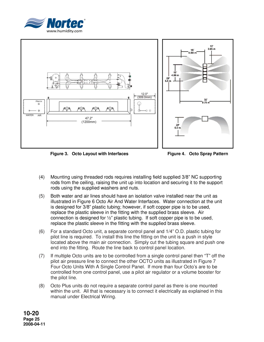
Figure 3. Octo Layout with Interfaces | Figure 4. Octo Spray Pattern |
(4)Mounting using threaded rods requires installing field supplied 3/8” NC supporting rods from the ceiling, raising the unit up into location and securing it to the support rods using the supplied washers and nuts.
(5)Both water and air lines should have an isolation valve installed near the unit as illustrated in Figure 6 Octo Air And Water Interfaces. Water connection at the unit is designed for 3/8” plastic tubing; however, if soft copper pipe is to be used, replace the plastic sleeve in the fitting with the supplied brass sleeve. Air connection is designed for ½” plastic tubing. If soft copper pipe is to be used, replace the plastic sleeve in the fitting with the supplied brass sleeve.
(6)For a standard Octo unit, a separate control panel and 1/4” O.D. plastic tubing for pilot line is required. To install this line the fitting on the unit is a push in style located above the main air connection. Simply cut the tubing square and push one end into the fitting. Route the line back to control panel location.
(7)If multiple Octo units are to be controlled from a single control panel then “T” off the pilot air pressure line to connect the other OCTO units as illustrated in Figure 7 Four Octo Units With A Single Control Panel. If more than four Octo’s are to be controlled from one control panel, use a pilot air regulator or a volume booster for the pilot line.
(8)Octo Plus units do not require a separate control panel as there is one mounted within the unit. All that is necessary is to connect it electrically as explained in this manual under Electrical Wiring.
Page 25