Chapter 2 Cabling the VPN Router and turning the power on 37
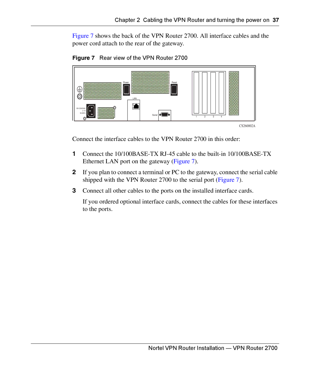
Figure 7 shows the back of the VPN Router 2700. All interface cables and the power cord attach to the rear of the gateway.
Figure 7 Rear view of the VPN Router 2700
Power | Reset |
|
|
|
| LAN |
|
|
|
|
|
|
| |
|
|
|
| |
Serial |
|
|
| |
| 2 | 3 | 4 | |
| 1 | |||
|
|
|
| CS260002A |
Connect the interface cables to the VPN Router 2700 in this order:
1Connect the
2If you plan to connect a terminal or PC to the gateway, connect the serial cable shipped with the VPN Router 2700 to the serial port (Figure 7).
3Connect all other cables to the ports on the installed interface cards.
If you ordered optional interface cards, connect the cables for these interfaces to the ports.