Chapter 2
Receiver Specifications
2.1System Architecture
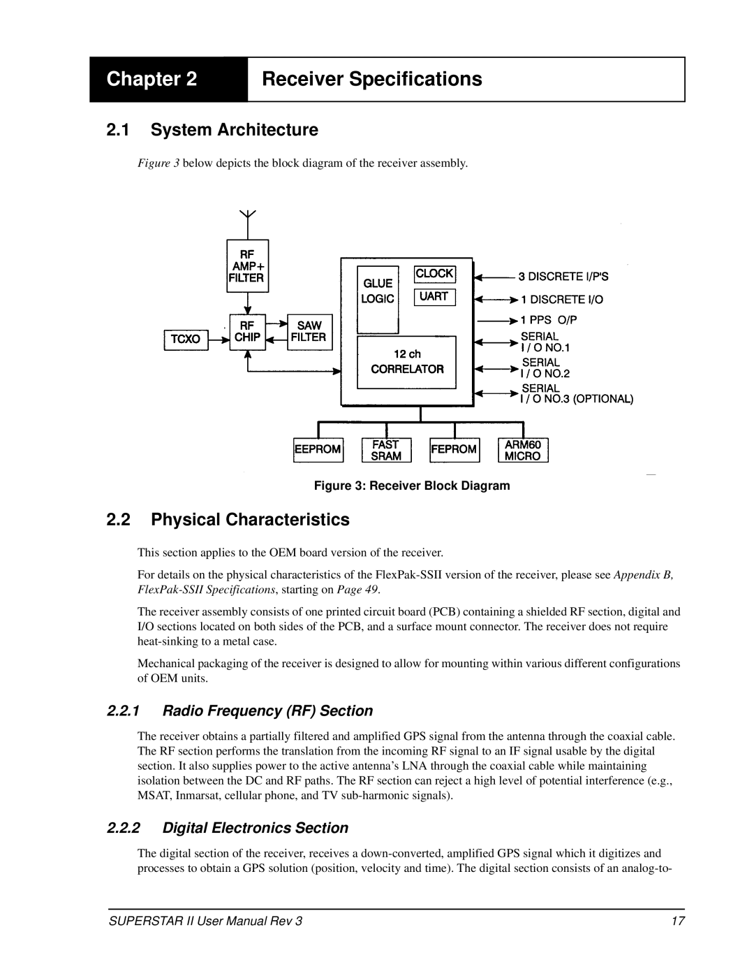
Figure 3 below depicts the block diagram of the receiver assembly.
Figure 3: Receiver Block Diagram
2.2Physical Characteristics
This section applies to the OEM board version of the receiver.
For details on the physical characteristics of the
The receiver assembly consists of one printed circuit board (PCB) containing a shielded RF section, digital and I/O sections located on both sides of the PCB, and a surface mount connector. The receiver does not require
Mechanical packaging of the receiver is designed to allow for mounting within various different configurations of OEM units.
2.2.1Radio Frequency (RF) Section
The receiver obtains a partially filtered and amplified GPS signal from the antenna through the coaxial cable. The RF section performs the translation from the incoming RF signal to an IF signal usable by the digital section. It also supplies power to the active antenna’s LNA through the coaxial cable while maintaining isolation between the DC and RF paths. The RF section can reject a high level of potential interference (e.g., MSAT, Inmarsat, cellular phone, and TV
2.2.2Digital Electronics Section
The digital section of the receiver, receives a
SUPERSTAR II User Manual Rev 3 | 17 |