Appendix A | Technical Specifications |
A.2.3 I/O Electrical Characteristics
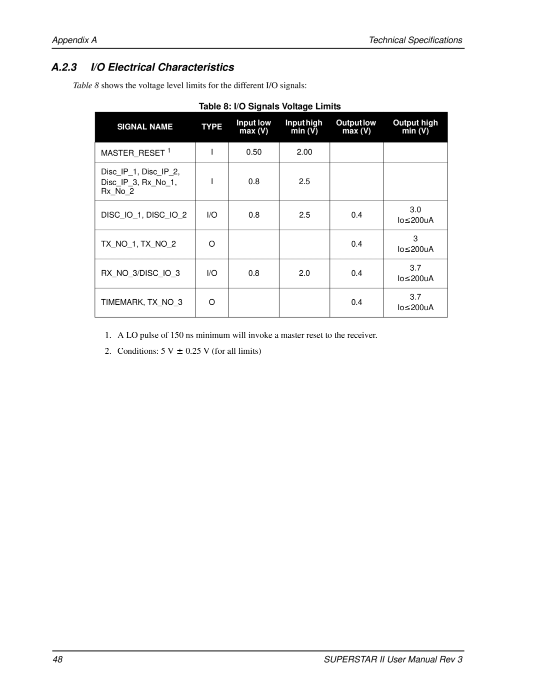
Table 8 shows the voltage level limits for the different I/O signals:
Table 8: I/O Signals Voltage Limits
SIGNAL NAME | TYPE | Input low | Input high | Output low | Output high | |
max (V) | min (V) | max (V) | min (V) | |||
|
| |||||
|
|
|
|
|
| |
MASTER_RESET 1 | I | 0.50 | 2.00 |
|
| |
Disc_IP_1, Disc_IP_2, | I | 0.8 | 2.5 |
|
| |
Disc_IP_3, Rx_No_1, |
|
| ||||
Rx_No_2 |
|
|
|
|
| |
|
|
|
|
|
| |
DISC_IO_1, DISC_IO_2 | I/O | 0.8 | 2.5 | 0.4 | 3.0 | |
Io≤200uA | ||||||
|
|
|
|
| ||
|
|
|
|
|
| |
TX_NO_1, TX_NO_2 | O |
|
| 0.4 | 3 | |
|
| Io≤200uA | ||||
|
|
|
|
| ||
|
|
|
|
|
| |
RX_NO_3/DISC_IO_3 | I/O | 0.8 | 2.0 | 0.4 | 3.7 | |
Io≤200uA | ||||||
|
|
|
|
| ||
|
|
|
|
|
| |
TIMEMARK, TX_NO_3 | O |
|
| 0.4 | 3.7 | |
|
| Io≤200uA | ||||
|
|
|
|
| ||
|
|
|
|
|
|
1.A LO pulse of 150 ns minimum will invoke a master reset to the receiver.
2.Conditions: 5 V ± 0.25 V (for all limits)
48 | SUPERSTAR II User Manual Rev 3 |