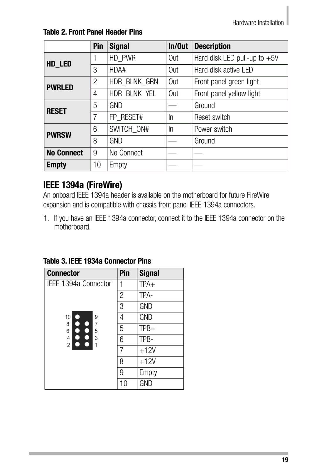
Table 2. Front Panel Header Pins |
| Hardware Installation |
| |||
|
| |||||
|
|
| ||||
|
|
|
|
|
| |
| Pin | Signal | In/Out | Description | ||
HD_LED | 1 | HD_PWR | Out | Hard disk LED | ||
|
|
|
|
| ||
3 | HDA# | Out | Hard disk active LED | |||
| ||||||
PWRLED | 2 | HDR_BLNK_GRN | Out | Front panel green light | ||
|
|
|
|
| ||
4 | HDR_BLNK_YEL | Out | Front panel yellow light | |||
| ||||||
RESET | 5 | GND | — | Ground | ||
|
|
|
|
| ||
7 | FP_RESET# | In | Reset switch | |||
| ||||||
PWRSW | 6 | SWITCH_ON# | In | Power switch | ||
|
|
|
|
| ||
8 | GND | — | Ground | |||
| ||||||
No Connect | 9 | No Connect | — | — | ||
Empty | 10 | Empty | — | — | ||
|
|
|
|
|
| |
IEEE 1394a (FireWire)
An onboard IEEE 1394a header is available on the motherboard for future FireWire expansion and is compatible with chassis front panel IEEE 1394a connectors.
1.If you have an IEEE 1394a connector, connect it to the IEEE 1394a connector on the motherboard.
Table 3. IEEE 1934a Connector Pins
Connector | Pin | Signal |
IEEE 1394a Connector | 1 | TPA+ |
|
|
|
| 2 | TPA- |
|
|
|
| 3 | GND |
|
|
|
| 4 | GND |
|
|
|
| 5 | TPB+ |
|
|
|
| 6 | TPB- |
|
|
|
| 7 | +12V |
|
|
|
| 8 | +12V |
|
|
|
| 9 | Empty |
|
|
|
| 10 | GND |
|
|
|
19
