¡ Semiconductor | MSM80C154S/83C154S |
Special Function Registers
Timer mode register (TMOD)
NAME | ADDRESS | MSB |
|
|
|
|
|
|
|
|
| LSB |
7 | 6 | 5 | 4 |
| 3 |
| 2 | 1 |
| 0 | ||
|
|
|
|
| ||||||||
|
|
|
|
|
|
|
|
|
|
|
|
|
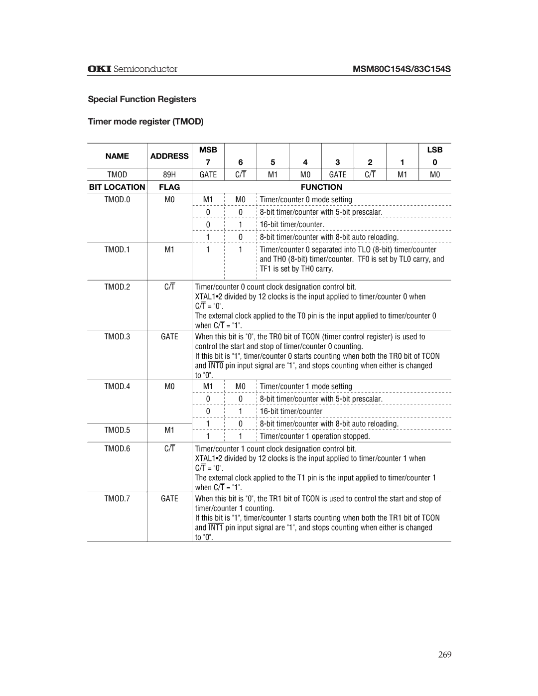
TMOD | 89H | GATE | C/T | M1 | M0 |
| GATE |
| C/T | M1 |
| M0 |
|
|
|
|
|
|
|
|
|
|
|
| |
BIT LOCATION | FLAG |
|
|
| FUNCTION |
|
|
|
| |||
|
|
|
|
|
|
|
|
|
|
|
| |
TMOD.0 | M0 | M1 | M0 | Timer/counter 0 mode setting |
|
|
|
| ||||
|
| 0 | 0 |
|
|
| ||||||
|
| 0 | 1 |
|
|
|
|
|
| |||
|
| 1 | 0 |
|
| |||||||
|
|
|
| Timer/counter 0 separated into TLO | ||||||||
TMOD.1 | M1 | 1 | 1 | |||||||||
|
|
|
| and TH0 | ||||||||
|
|
|
| TF1 is set by TH0 carry. |
|
|
|
| ||||
|
|
|
|
|
|
|
|
|
|
|
| |
TMOD.2 | C/T | Timer/counter 0 count clock designation control bit. |
|
|
|
| ||||||
|
| XTAL1•2 divided by 12 clocks is the input applied to timer/counter 0 when |
| |||||||||
|
| C/T = "0". |
|
|
|
|
|
|
|
|
|
|
|
| The external clock applied to the T0 pin is the input applied to timer/counter 0 | ||||||||||
|
| when C/T = "1". |
|
|
|
|
|
|
|
|
| |
TMOD.3 | GATE | When this bit is "0", the TR0 bit of TCON (timer control register) is used to |
| |||||||||
|
| control the start and stop of timer/counter 0 counting. |
|
|
|
| ||||||
|
| If this bit is "1", timer/counter 0 starts counting when both the TR0 bit of TCON | ||||||||||
|
| and INT0 pin input signal are "1", and stops counting when either is changed | ||||||||||
|
| to "0". |
|
|
|
|
|
|
|
|
|
|
TMOD.4 | M0 | M1 | M0 | Timer/counter 1 mode setting |
|
|
|
| ||||
|
| 0 | 0 |
|
|
| ||||||
|
| 0 | 1 |
|
|
|
|
|
| |||
|
| 1 | 0 |
| ||||||||
TMOD.5 | M1 |
| ||||||||||
1 | 1 | Timer/counter 1 operation stopped. |
|
|
| |||||||
|
|
|
|
| ||||||||
|
|
|
|
|
|
|
|
|
|
|
| |
TMOD.6 | C/T | Timer/counter 1 count clock designation control bit. |
|
|
|
| ||||||
|
| XTAL1•2 divided by 12 clocks is the input applied to timer/counter 1 when |
| |||||||||
|
| C/T = "0". |
|
|
|
|
|
|
|
|
|
|
|
| The external clock applied to the T1 pin is the input applied to timer/counter 1 | ||||||||||
|
| when C/T = "1". |
|
|
|
|
|
|
|
|
| |
TMOD.7 | GATE | When this bit is "0", the TR1 bit of TCON is used to control the start and stop of | ||||||||||
|
| timer/counter 1 counting. |
|
|
|
|
|
|
|
| ||
|
| If this bit is "1", timer/counter 1 starts counting when both the TR1 bit of TCON | ||||||||||
|
| and INT1 pin input signal are "1", and stops counting when either is changed | ||||||||||
|
| to "0". |
|
|
|
|
|
|
|
|
|
|
269
