MSM80C154S/83C154S |
|
|
|
|
|
|
|
| ¡ Semiconductor | |||||
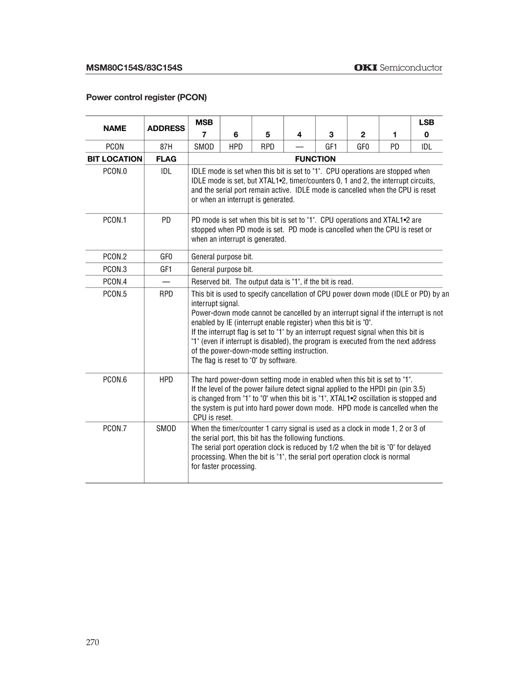
Power control register (PCON) |
|
|
|
|
|
|
|
|
|
|
|
| ||
|
|
|
|
|
|
|
|
|
|
|
|
|
|
|
NAME | ADDRESS | MSB |
|
|
|
|
|
|
|
|
|
| LSB | |
7 | 6 |
| 5 |
| 4 | 3 |
| 2 | 1 |
| 0 |
| ||
|
|
|
|
|
|
| ||||||||
|
|
|
|
|
|
|
|
|
|
|
|
|
|
|
PCON | 87H | SMOD | HPD |
| RPD |
| — | GF1 |
| GF0 | PD |
| IDL | |
BIT LOCATION | FLAG |
|
|
|
|
| FUNCTION |
|
|
|
|
| ||
|
|
|
|
|
|
|
|
|
|
| ||||
PCON.0 | IDL | IDLE mode is set when this bit is set to "1". CPU operations are stopped when | ||||||||||||
|
| IDLE mode is set, but XTAL1•2, timer/counters 0, 1 and 2, the interrupt circuits, | ||||||||||||
|
| and the serial port remain active. IDLE mode is cancelled when the CPU is reset | ||||||||||||
|
| or when an interrupt is generated. |
|
|
|
|
|
|
|
| ||||
|
|
|
|
|
|
|
|
|
|
| ||||
PCON.1 | PD | PD mode is set when this bit is set to "1". CPU operations and XTAL1•2 are | ||||||||||||
|
| stopped when PD mode is set. PD mode is cancelled when the CPU is reset or | ||||||||||||
|
| when an interrupt is generated. |
|
|
|
|
|
|
|
| ||||
|
|
|
|
|
|
|
|
|
|
|
|
|
|
|
PCON.2 | GF0 | General purpose bit. |
|
|
|
|
|
|
|
|
|
| ||
|
|
|
|
|
|
|
|
|
|
|
|
|
|
|
PCON.3 | GF1 | General purpose bit. |
|
|
|
|
|
|
|
|
|
| ||
|
|
|
|
|
|
|
|
|
|
|
|
| ||
PCON.4 | — | Reserved bit. The output data is "1", if the bit is read. |
|
|
|
|
| |||||||
|
|
|
|
|
|
|
|
|
|
| ||||
PCON.5 | RPD | This bit is used to specify cancellation of CPU power down mode (IDLE or PD) by an | ||||||||||||
|
| interrupt signal. |
|
|
|
|
|
|
|
|
|
| ||
|
| |||||||||||||
|
| enabled by IE (interrupt enable register) when this bit is "0". |
|
|
|
| ||||||||
|
| If the interrupt flag is set to "1" by an interrupt request signal when this bit is | ||||||||||||
|
| "1" (even if interrupt is disabled), the program is executed from the next address | ||||||||||||
|
| of the |
|
|
|
|
| |||||||
|
| The flag is reset to "0" by software. |
|
|
|
|
|
|
| |||||
|
|
|
|
|
|
|
|
|
|
|
| |||
PCON.6 | HPD | The hard |
|
| ||||||||||
|
| If the level of the power failure detect signal applied to the HPDI pin (pin 3.5) | ||||||||||||
|
| is changed from "1" to "0" when this bit is "1", XTAL1•2 oscillation is stopped and | ||||||||||||
|
| the system is put into hard power down mode. HPD mode is cancelled when the | ||||||||||||
|
| CPU is reset. |
|
|
|
|
|
|
|
|
|
| ||
PCON.7 | SMOD | When the timer/counter 1 carry signal is used as a clock in mode 1, 2 or 3 of | ||||||||||||
|
| the serial port, this bit has the following functions. |
|
|
|
|
| |||||||
|
| The serial port operation clock is reduced by 1/2 when the bit is "0" for delayed | ||||||||||||
|
| processing. When the bit is "1", the serial port operation clock is normal |
|
| ||||||||||
|
| for faster processing. |
|
|
|
|
|
|
|
|
|
| ||
|
|
|
|
|
|
|
|
|
|
|
|
|
|
|
270