3.3.9I/O Selection Control Register
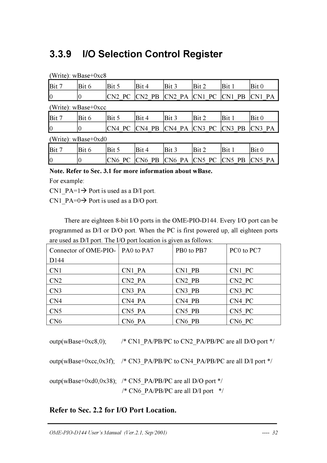
(Write): wBase+0xc8
Bit 7 | Bit 6 | Bit 5 | Bit 4 | Bit 3 | Bit 2 | Bit 1 | Bit 0 |
0 | 0 | CN2_PC | CN2_PB | CN2_PA | CN1_PC | CN1_PB | CN1_PA |
(Write): wBase+0xcc |
|
|
|
|
|
| |
Bit 7 | Bit 6 | Bit 5 | Bit 4 | Bit 3 | Bit 2 | Bit 1 | Bit 0 |
0 | 0 | CN4_PC | CN4_PB | CN4_PA | CN3_PC | CN3_PB | CN3_PA |
(Write): wBase+0xd0 |
|
|
|
|
|
| |
Bit 7 | Bit 6 | Bit 5 | Bit 4 | Bit 3 | Bit 2 | Bit 1 | Bit 0 |
0 | 0 | CN6_PC | CN6_PB | CN6_PA | CN5_PC | CN5_PB | CN5_PA |
Note. Refer to Sec. 3.1 for more information about wBase.
For example:
CN1_PA=1Æ Port is used as a D/I port.
CN1_PA=0Æ Port is used as a D/O port.
There are eighteen
Connector of | PA0 to PA7 | PB0 to PB7 |
| PC0 to PC7 |
D144 |
|
|
|
|
CN1 | CN1_PA | CN1_PB |
| CN1_PC |
CN2 | CN2_PA | CN2_PB |
| CN2_PC |
CN3 | CN3_PA | CN3_PB |
| CN3_PC |
CN4 | CN4_PA | CN4_PB |
| CN4_PC |
CN5 | CN5_PA | CN5_PB |
| CN5_PC |
CN6 | CN6_PA | CN6_PB |
| CN6_PC |
outp(wBase+0xc8,0); | /* CN1_PA/PB/PC to CN2_PA/PB/PC are all D/O port */ | |||
outp(wBase+0xcc,0x3f); | /* CN3_PA/PB/PC to CN4_PA/PB/PC are all D/I port */ | |||
outp(wBase+0xd0,0x38); | /* CN5_PA/PB/PC are all D/O port */ | |||
| /* CN6_PA/PB/PC are all D/I port | */ |
| |
Refer to Sec. 2.2 for I/O Port Location.
|