3.3The I/O Address Map
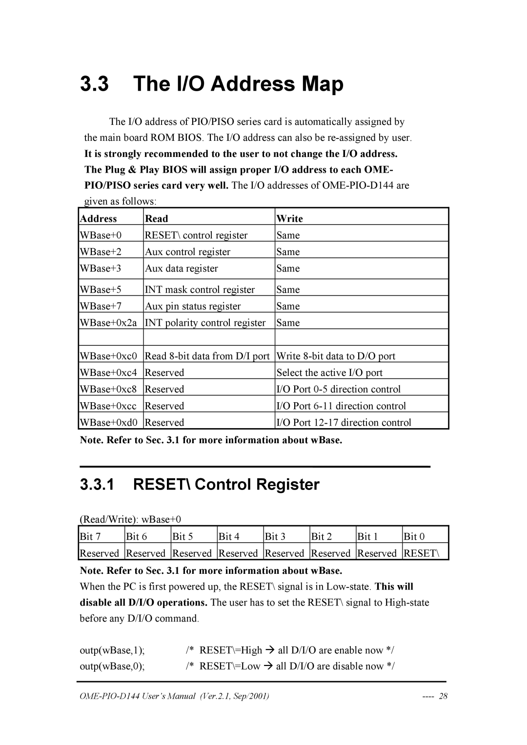
The I/O address of PIO/PISO series card is automatically assigned by the main board ROM BIOS. The I/O address can also be
It is strongly recommended to the user to not change the I/O address. The Plug & Play BIOS will assign proper I/O address to each OME- PIO/PISO series card very well. The I/O addresses of
given as follows:
Address | Read | Write |
WBase+0 | RESET\ control register | Same |
WBase+2 | Aux control register | Same |
WBase+3 | Aux data register | Same |
|
|
|
WBase+5 | INT mask control register | Same |
WBase+7 | Aux pin status register | Same |
WBase+0x2a | INT polarity control register | Same |
|
|
|
WBase+0xc0 | Read | Write |
WBase+0xc4 | Reserved | Select the active I/O port |
WBase+0xc8 | Reserved | I/O Port |
WBase+0xcc | Reserved | I/O Port |
WBase+0xd0 | Reserved | I/O Port |
Note. Refer to Sec. 3.1 for more information about wBase.
3.3.1RESET\ Control Register
(Read/Write): wBase+0
Bit 7 | Bit 6 | Bit 5 | Bit 4 | Bit 3 | Bit 2 | Bit 1 | Bit 0 |
Reserved | Reserved | Reserved | Reserved | Reserved | Reserved | Reserved | RESET\ |
Note. Refer to Sec. 3.1 for more information about wBase.
When the PC is first powered up, the RESET\ signal is in
outp(wBase,1); | /* | RESET\=High Æ all D/I/O are enable now */ |
outp(wBase,0); | /* | RESET\=Low Æ all D/I/O are disable now */ |
|
