m | |
|
-
CDE681 Part 2 - Installation
1. Install a pipe tee of appropriate size (‘x to 2 inch) and material into the process pipe. If necessary, screw a
avoid leaks. Recommendation: UseTeflon tape or pipe
sealant with Teflon. (Exception: For higher temperature solutions, sealing with Teflon tape may not be adequate.)
SENSOR CABLE 6.1FT)M (20
SENSOR
CLEARANCE
FOR SENSOR
l/2OR3/4
COMPRESSION FIrrING
i/2OR3/4”NPT4
TREADED TEE
DIMENSIONS(in)mm
u
FLOW
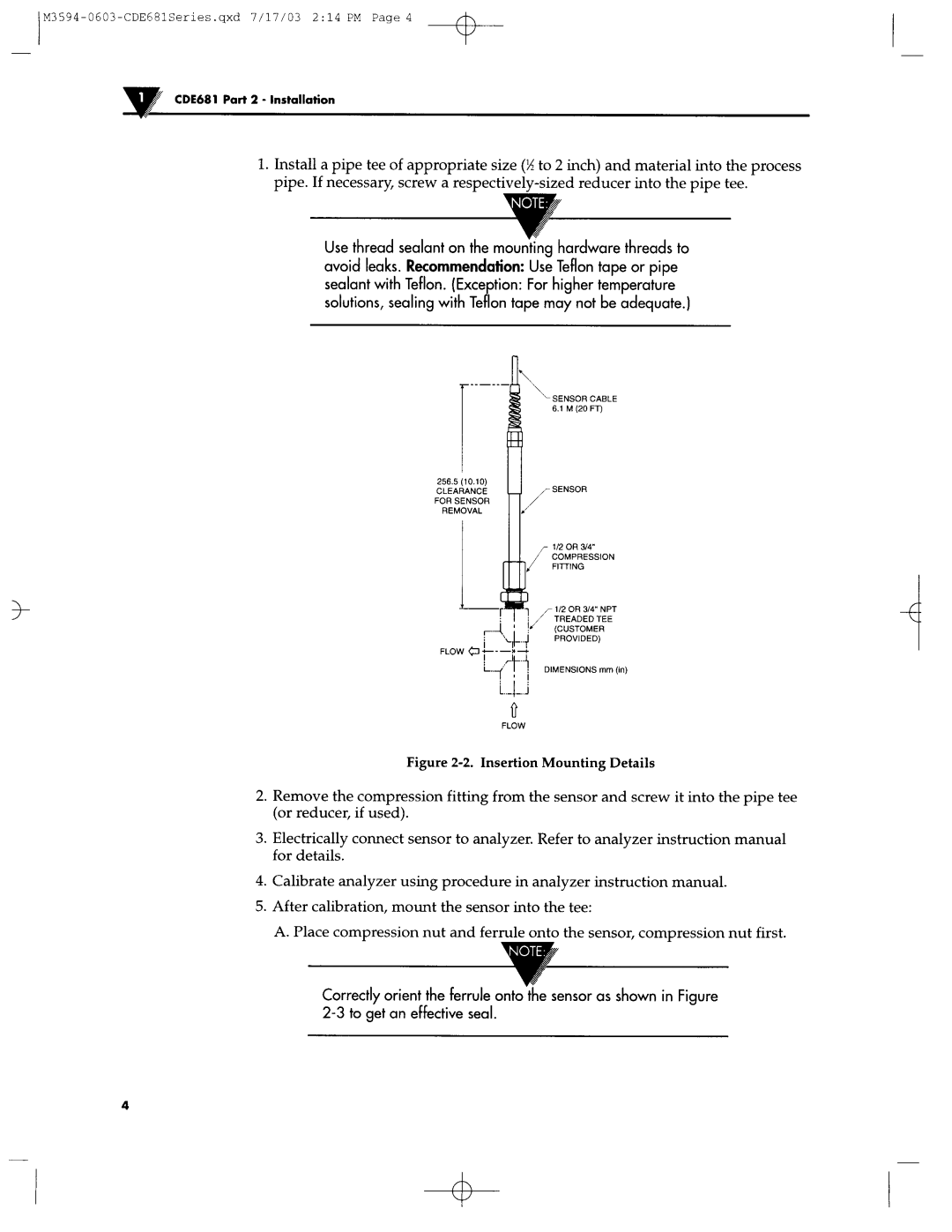
Figure 2-2. Insertion Mounting Details
2.Remove the compression fitting from the sensor and screw it into the pipe tee (or reducer, if used).
3.Electrically connect sensor to analyzer. Refer to analyzer instruction manual for details.
4.Calibrate analyzer using procedure in analyzer instruction manual.
5.After calibration, mount the sensor into the tee:
A. Place comoression nut and ferrule onto the sensor. | comtxession | nut first. |
I | ’ I |
|
Correctly orient the ferrule ontoXe sensor as shown in Figure
4
