M3594m0603mCDE681Series.qxd 7/17/03 2:14 PM Page 3 | m |
CDE681 Part 2 - lnstallatio
PART TWO - INSTALLATION
SECTION 1 - LOCATION REQUIREMENTS
Locate the sensor as close as possible to the measuring instrument. Do not exceed a distance of 91 m (300 feet) between the sensor and instrument.
SECTION 2 - Mounting
The
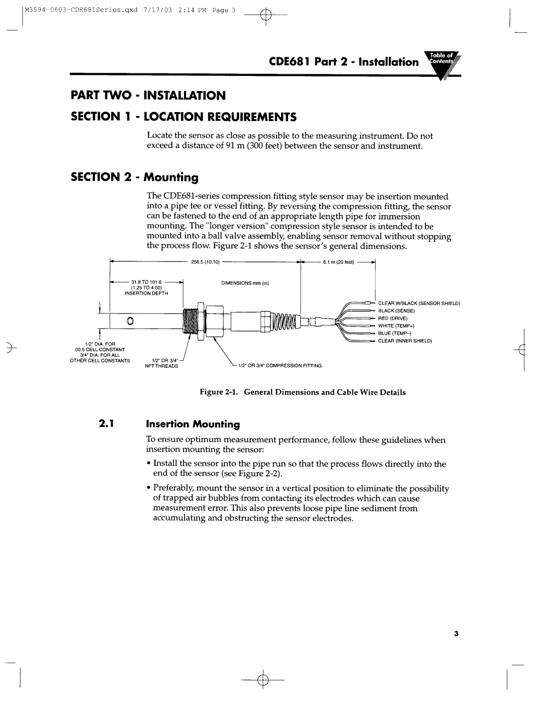
mounting. The “longer version ” compression style sensor is intended to be mounted into a ball valve assembly, enabling sensor removal without stopping the process flow. Figure
.
f
CLEAR SHIELD)W/BLACK(SEN
BLACK(SENSE)
RED(DRIVE)
WHITE(TEMP+)
CLEAR(INNER SHIELD
l/2’DIA. FOR
00.5CELL CONSTANT
3/4’DIA. FOR ALL 1
OTHER CELLl/2’OR3/4’CONSTANTS\
NPT THREADS
Figure 2-l. General Dimensions and Cable Wire Details
2. 1 Insertion Mounting
To ensure optimum measurement performance, follow these guidelines when insertion mounting the sensor:
??Install the sensor into the pipe run so that the process flows directly into the end of the sensor (see Figure
??Preferably, mount the sensor in a vertical position to eliminate the possibility of trapped air bubbles from contacting its electrodes which can cause measurement error. This also prevents loose pipe line sediment from accumulating and obstructing the sensor electrodes.
3