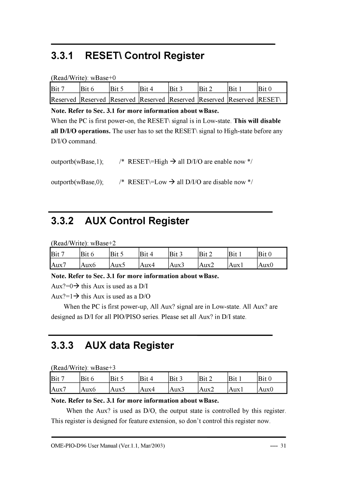
3.3.1RESET\ Control Register
(Read/Write): wBase+0
Bit 7 | Bit 6 | Bit 5 | Bit 4 | Bit 3 | Bit 2 | Bit 1 | Bit 0 |
Reserved Reserved Reserved Reserved Reserved Reserved Reserved RESET\
Note. Refer to Sec. 3.1 for more information about wBase.
When the PC is first
outportb(wBase,1); | /* | RESET\=High Æ all D/I/O are enable now */ |
outportb(wBase,0); | /* | RESET\=Low Æ all D/I/O are disable now */ |
3.3.2AUX Control Register
(Read/Write): wBase+2
Bit 7 | Bit 6 | Bit 5 | Bit 4 | Bit 3 | Bit 2 | Bit 1 | Bit 0 |
Aux7 | Aux6 | Aux5 | Aux4 | Aux3 | Aux2 | Aux1 | Aux0 |
Note. Refer to Sec. 3.1 for more information about wBase.
Aux?=0Æ this Aux is used as a D/I Aux?=1Æ this Aux is used as a D/O
When the PC is first
3.3.3AUX data Register
(Read/Write): wBase+3
Bit 7 | Bit 6 | Bit 5 | Bit 4 | Bit 3 | Bit 2 | Bit 1 | Bit 0 |
Aux7 | Aux6 | Aux5 | Aux4 | Aux3 | Aux2 | Aux1 | Aux0 |
Note. Refer to Sec. 3.1 for more information about wBase.
When the Aux? is used as D/O, the output state is controlled by this register. This register is designed for feature extension, so don’t control this register now.