Omega Engineering manual Interrupt Block Diagram of OME-PIO-D96, INTCHAN3

Models: OME-PIO-D96

1 51
Download 51 pages 21.71 Kb
Page 12
Image 12

2.5.1Interrupt Block Diagram of OME-PIO-D96
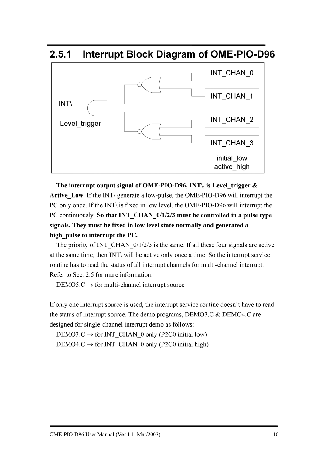
 

INT_CHAN_0

INT\

INT_CHAN_1


Level_trigger

INT_CHAN_2


INT_CHAN_3


initial_low


active_high

The interrupt output signal of OME-PIO-D96, INT\, is Level_trigger & Active_Low. If the INT\ generate a low-pulse, the OME-PIO-D96 will interrupt the PC only once. If the INT\ is fixed in low level, the OME-PIO-D96 will interrupt the PC continuously. So that INT_CHAN_0/1/2/3 must be controlled in a pulse type signals. They must be fixed in low level state normally and generated a high_pulse to interrupt the PC.

The priority of INT_CHAN_0/1/2/3 is the same. If all these four signals are active at the same time, then INT\ will be active only once a time. So the interrupt service routine has to read the status of all interrupt channels for multi-channel interrupt. Refer to Sec. 2.5 for mare information.

DEMO5.C for multi-channel interrupt source

If only one interrupt source is used, the interrupt service routine doesn’t have to read the status of interrupt source. The demo programs, DEMO3.C & DEMO4.C are designed for single-channel interrupt demo as follows:

DEMO3.C for INT_CHAN_0 only (P2C0 initial low) DEMO4.C for INT_CHAN_0 only (P2C0 initial high)

OME-PIO-D96 User Manual (Ver.1.1, Mar/2003)

---- 10

Page 12
Image 12
Omega Engineering manual Interrupt Block Diagram of OME-PIO-D96, INTCHAN3