2.2 Digital to Analog Converters

The digital to analog (D/A) section of the D AQ-16 consists of two independent 12-bit
multiplying D/A converters, and two independe nt two-stage output ampli fiers. Digita l data,
(output to the D/A converter by the CPU), is converted to an analog voltage by the D/A
converter, amplified by the output ampli fiers and be comes output to the 62 pin connector at
CN1. The D/A converters used on the DA Q-16 ar e 12- bi t resol ution converter s. Of the 16 bi ts
written to the D/A, only the 12 least signifi cant bits (D0 - D1 1) are used for the conversi on.
The 4 most significant bits (D12 - D15) are ignored.
The DAQ-16 implements multiplying D/A converters w hich makes the analog output
proportional to a reference voltage applied to the D/A. Under nor mal circumstances, the
reference voltage should be applied from the internal +5V reference source. An external
reference voltage may also be supplied to the D /A. This input from the D-62 connector should
not exceed 5 volts and has a typical input impedance of 7.5Kohms. The D/A reference voltage
source is selected using jumper J3 as illustrated in Figure 2-4.
4 5 6
1 2 3
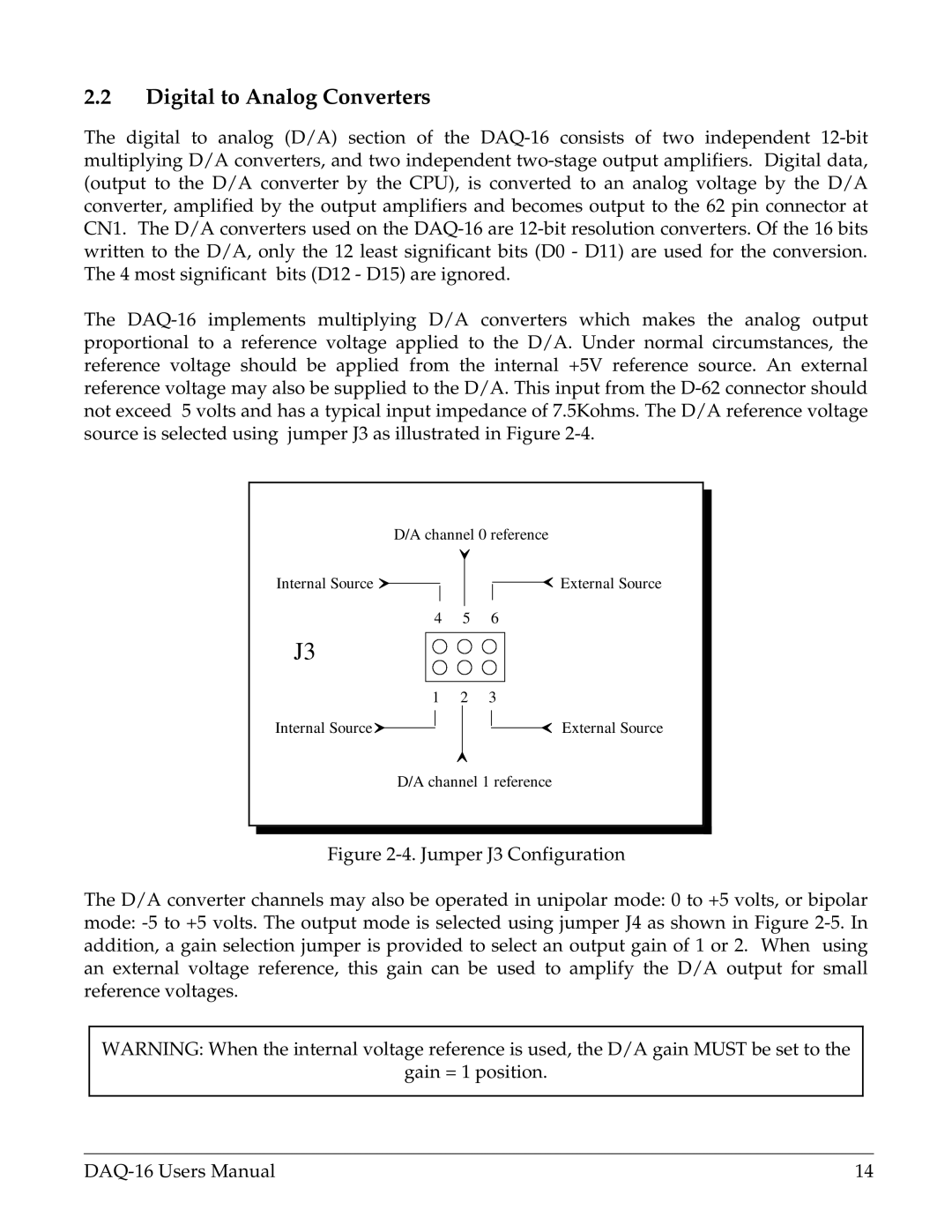
D/A channel 0 reference
External Source
External Source
Internal Source
Internal Source
D/A channel 1 reference
J3
Figure 2-4. Jumper J3 Configuration
The D/A converter channels may also be operated in unipol ar mod e: 0 to +5 vol ts, or bipolar
mode: -5 to +5 volts. The output mode is selected using jumper J4 as shown in Figure 2-5. In
addition, a gain selection jumper is provided to select an output gain of 1 or 2. When using
an external voltage reference, this gain can b e used to amplify the D/A output for small
reference voltages.
WARNING: When the internal voltage reference is used, the D/A gain MUST be set to the
gain = 1 position.
DAQ-16 Users Manual 14