When configured for a
tadd = 100ns * [N1 * N2]
To minimize the amount of additional time required for the first sample, select clock dividers such that N1 and N2 are as small as possible and N3 is as large as possible. Using the equations above, the minimum and maximum data sampling rates and the amount of additional time required for the first sample can be calculated.
Maximum sampling rate: | Minimum sampling rate: |
N1 = 2, N2 = 2, N3 = 25 | N1 = 65535, N2 = 65535, N3 = 65535 |
t = 100 x 10−9 * [(2)*(2)*(25)] | t = 100 x 10−9 * [(65535)*(65535)*(65535)] |
t = 100 x 10−9 * 100 | t = 100 x 10−9 * [2.815 x 1014 ] |
t = 10 us | t = 28.146 x 10⁶ sec |
f = 10 x 106 / [(2)*(2)*(25)] | t = 325 days, 18 hours, 23 minutes, 29 sec |
f = 10 x 106 / 100 | f = 10 x 106 / [(65535)*(65535)*(65535 )] |
f = 100 Khz | f = 10 x 106 / [2.815 x 10¹⁴ ] |
| f = 35.529 nHz |
tadd = 100 x 10−9 * [2 * 2] | tadd = 100 x 10−9 * [65535 * 65535] |
tadd = 100 x 10−9 * 4 | tadd = 100 x 10−9 * [4.295 x 109 ] |
tadd = 400 ns | tadd = 429.5 sec |
2.5.2External Clock
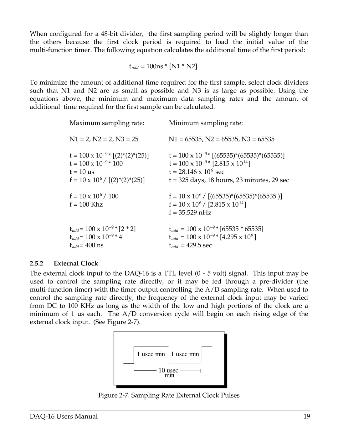
The external clock input to the
1 usec min 1 usec min
10 usec min
Figure 2-7. Sampling Rate External Clock Pulses
19 |