5 6 7 8
J4
1 2 3 4
Channel 0 select
Channel 0 gain ![]()
![]() Channel 1 gain
Channel 1 gain
Channel 1 select
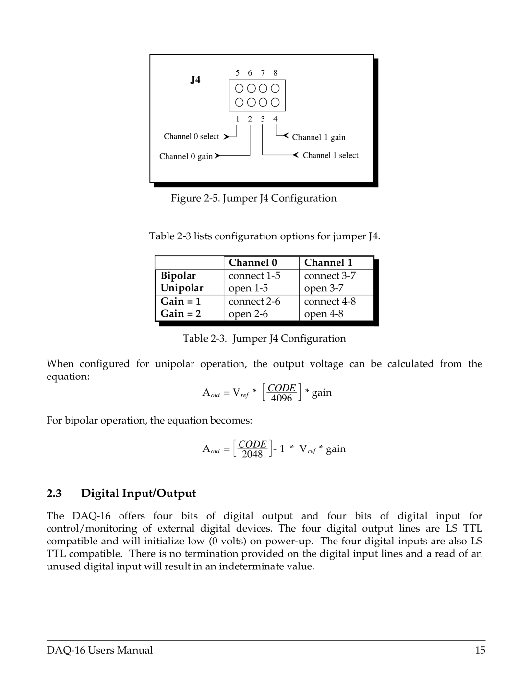
Figure 2-5. Jumper J4 Configuration
Table 2-3 lists configuration options for jumper J4.
|
| Channel 0 | Channel 1 |
| |
|
|
| |||
| Bipolar | connect | connect |
|
|
| Unipolar | open | open |
| |
| Gain = 1 | connect | connect |
|
|
| Gain = 2 | open | open |
| |
|
|
|
|
|
|
Table
When configured for unipolar operation, the output voltage can be calculated from the equation:
Aout = Vref *
For bipolar operation, the equation becomes:
CODE
4096
* gain
Aout =
CODE
2048
- 1 * Vref * gain
2.3Digital Input/Output
The
15 |
