POWER
Power connection should be made to the three terminal connector as shown in figure 3. Also, make note that it is very important that the power line inputs and the power ground are not switched. Doing so will permanently damage the instrument. Refer to Figure 3 for proper connections. For convenience, the printed circuit board is labeled
L1 L2 GND on the under side of three terminal power connector. For instruments with the 15Vdc power option, L1 = negative supply and L2 = positive supply.
NOTE: WHILE CONNECTING POWER TO THE UNIT, MAKE SURE THAT AC POWER LINE L1 OR L2 IS NOT ACCIDENTALLY CONNECTED TO GROUND (GND) TERMINAL. THIS WILL RESULT IN PERMANENT DAMAGE TO THE INSTRUMENT.
DOUBLE CHECK THE CONNECTIONS BEFORE APPLYING POWER!!
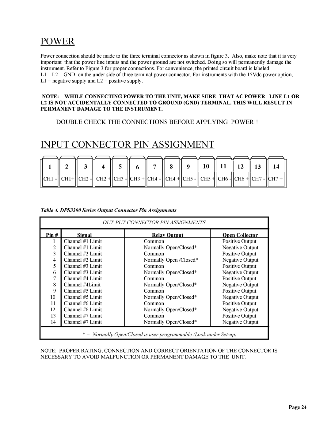
INPUT CONNECTOR PIN ASSIGNMENT
1
CH1 -
2 ![]()
![]() 3
3
CH1+ CH2 -
4 ![]()
![]() 5
5 ![]()
![]() 6
6 ![]()
![]() 7
7
CH2 + CH3 - CH3 + CH4 -
8 ![]()
![]() 9
9
CH4 + CH5 -
10 | 11 | 12 | 13 |
CH5 + CH6 - CH6 + CH7 -
14
CH7 +
Table 4. DPS3300 Series Output Connector Pin Assignments
| Pin # | Signal | Relay Output | Open Collector | |
| 1 | Channel #1 Limit | Common | Positive Output |
|
| 2 | Channel #1 Limit | Normally Open/Closed* | Negative Output | |
| 3 | Channel #2 Limit | Common | Positive Output | |
| 4 | Channel #2 Limit | Normally Open /Closed* | Negative Output | |
| 5 | Channel #3 Limit | Common | Positive Output | |
| 6 | Channel #3 Limit | Normally Open/Closed* | Negative Output | |
| 7 | Channel #4 Limit | Common | Positive Output | |
| 8 | Channel #4Limit | Normally Open/Closed* | Negative Output | |
| 9 | Channel #5 Limit | Common | Positive Output | |
| 10 | Channel #5 Limit | Normally Open/Closed* | Negative Output | |
| 11 | Channel #6 Limit | Common | Positive Output | |
| 12 | Channel #6 Limit | Normally Open/Closed* | Negative Output | |
| 13 | Channel #7 Limit | Common | Positive Output | |
| 14 | Channel #7 Limit | Normally Open/Closed* | Negative Output | |
* = Normally Open/Closed is user programmable (Look under
NOTE: PROPER RATING, CONNECTION AND CORRECT ORIENTATION OF THE CONNECTOR IS NECESSARY TO AVOID MALFUNCTION OR PERMANENT DAMAGE TO THE UNIT.
Page 24