The channel numbers in Display Option #6 start with 'CH1 dIF' and go up to 'CH7 dIF' (CH4 dIF for 4 channel units). Following this the display jumps back to Option #1 (elapsed time), and the cycle is repeated.
Setup For Display Time
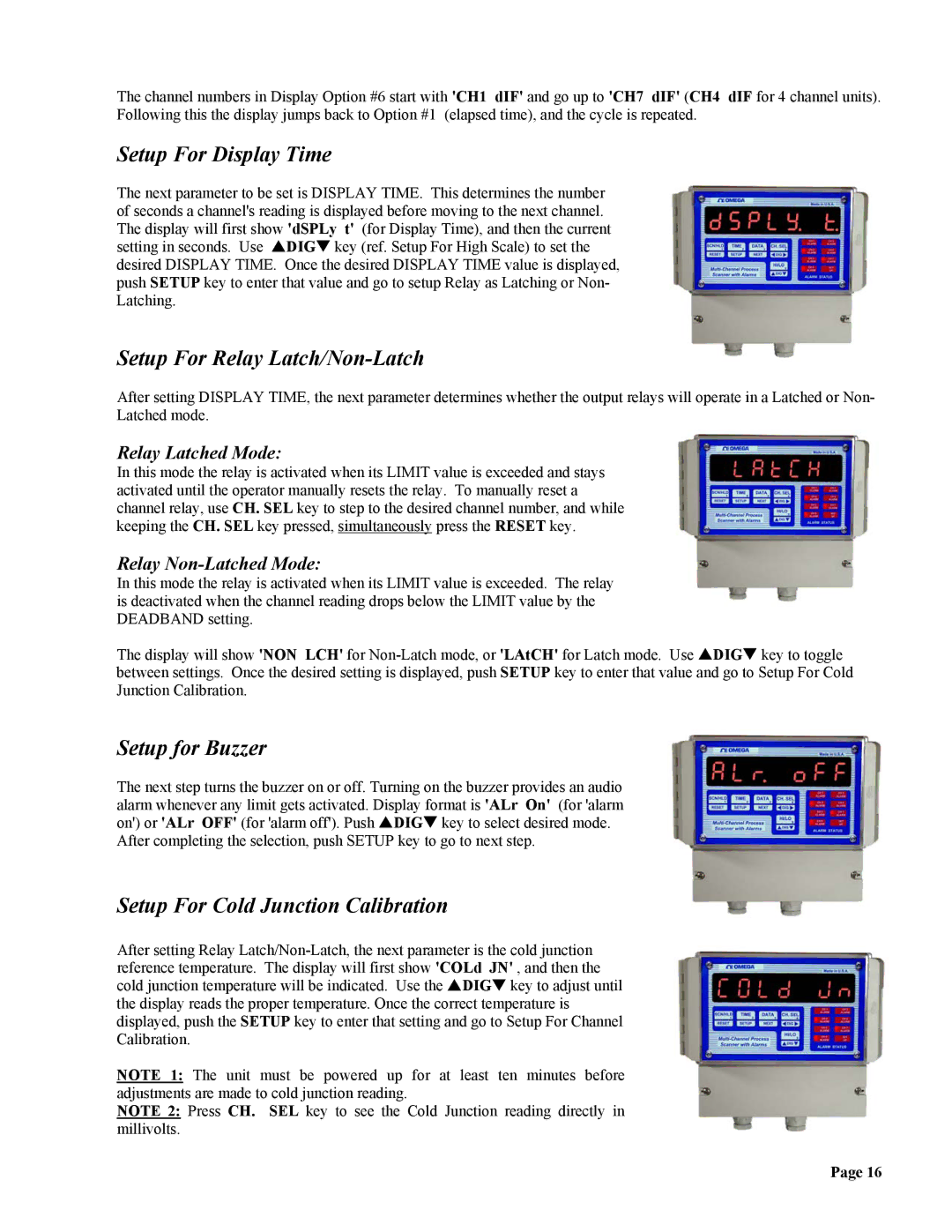
The next parameter to be set is DISPLAY TIME. This determines the number of seconds a channel's reading is displayed before moving to the next channel. The display will first show 'dSPLy t' (for Display Time), and then the current setting in seconds. Use SDIGT key (ref. Setup For High Scale) to set the desired DISPLAY TIME. Once the desired DISPLAY TIME value is displayed, push SETUP key to enter that value and go to setup Relay as Latching or Non- Latching.
Setup For Relay Latch/Non-Latch
After setting DISPLAY TIME, the next parameter determines whether the output relays will operate in a Latched or Non- Latched mode.
Relay Latched Mode:
In this mode the relay is activated when its LIMIT value is exceeded and stays activated until the operator manually resets the relay. To manually reset a channel relay, use CH. SEL key to step to the desired channel number, and while keeping the CH. SEL key pressed, simultaneously press the RESET key.
Relay Non-Latched Mode:
In this mode the relay is activated when its LIMIT value is exceeded. The relay is deactivated when the channel reading drops below the LIMIT value by the DEADBAND setting.
The display will show 'NON LCH' for
Setup for Buzzer
The next step turns the buzzer on or off. Turning on the buzzer provides an audio alarm whenever any limit gets activated. Display format is 'ALr On' (for 'alarm on') or 'ALr OFF' (for 'alarm off'). Push SDIGT key to select desired mode.
After completing the selection, push SETUP key to go to next step.
Setup For Cold Junction Calibration
After setting Relay
NOTE 1: The unit must be powered up for at least ten minutes before adjustments are made to cold junction reading.
NOTE 2: Press CH. SEL key to see the Cold Junction reading directly in millivolts.
Page 16