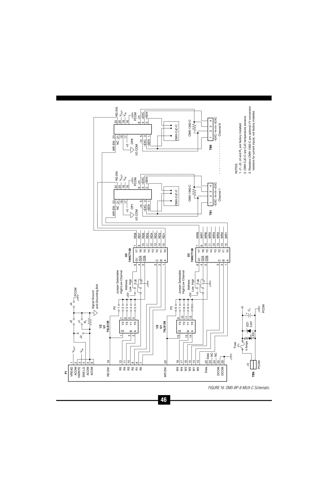
OM5-C specifications
Introducing the Omega Vehicle Security OM5-C, a cutting-edge vehicle security system designed to provide unparalleled protection against theft and unauthorized access. The OM5-C is engineered for modern vehicles, integrating advanced technologies to safeguard your investment while enhancing convenience and peace of mind.One of the standout features of the OM5-C is its advanced immobilizer technology. This feature ensures that even if a thief manages to access your vehicle, they will be unable to start the engine without the proper authentication. The OM5-C uses a sophisticated algorithm that communicates with a unique key fob, making it virtually impossible for unauthorized users to bypass the system.
Another significant characteristic of the Omega Vehicle Security OM5-C is its real-time GPS tracking system. Users can remotely monitor their vehicle's location through a dedicated mobile app, which allows for instant alerts if your vehicle is moved without authorization. This not only aids in recovery in the event of theft but also provides peace of mind knowing you can always keep an eye on your vehicle’s whereabouts.
The OM5-C also boasts motion sensors that can detect any unauthorized movement, triggering an alarm to deter potential thieves. In addition, the system features advanced diagnostic capabilities, allowing users to receive notifications about the status of various vehicle components, further ensuring that everything is functioning within normal parameters.
In terms of installation, the Omega Vehicle Security OM5-C is designed for ease and efficiency. It can be installed in a wide variety of vehicles, making it versatile for different types of users. The system is compatible with both standard and luxury vehicles, ensuring comprehensive security solutions for everyone.
The user-friendly interface provided by the OM5-C mobile app allows for easy customization of alerts and settings, allowing users to tailor the system to their specific needs. Users can seamlessly manage alarm settings, track vehicle movements, and even pre-load emergency contacts directly from their smartphones.
Overall, the Omega Vehicle Security OM5-C stands out as a premier choice for vehicle protection, combining innovative technology with user-centric features. This state-of-the-art security system not only defends against theft but also enhances the overall security experience for vehicle owners, making it an invaluable investment for safeguarding automobiles.

