DV-SP1000 DV-SP1000E
Important Safety Instructions
Avis
Precautions
Fare
Precautions
Modèle pour les Canadien
Never Touch this Unit with Wet Hands
Moisture condensation may damage this unit
Contents
DV-SP1000/DV-SP1000E Features
Introduction
Supplied Accessories
Introduction
Supported Discs
Unsupported DVD Features
Disc Notes
DVD-Video Regions
MP3 & Jpeg Compatibility
Disc Content Organization
Video CDs
Function Support
Storing Discs
Cleaning Discs
Handling Discs
Copyright
Hdmi High Definition Multimedia Interface
Terminology
Jpeg Joint Photographic Experts Group
MPEG2 Moving Picture Experts Group
MPEG1 Moving Picture Experts Group
Vlsc Vector Linear Shaping Circuitry
Using the Remote Controller
Installing the Remote’s Batteries
Before Use
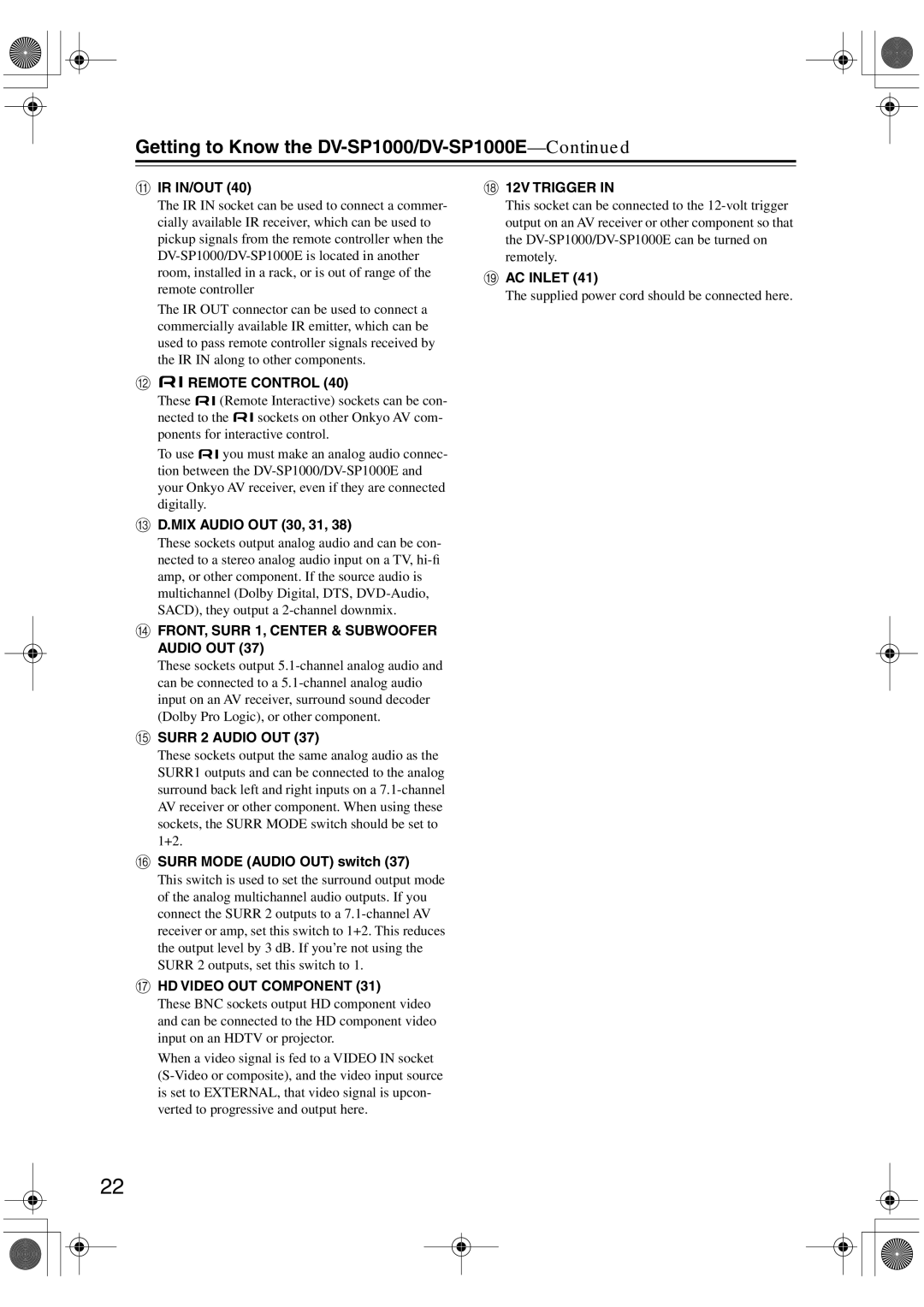
Getting to Know the DV-SP1000/DV-SP1000E
Front Panel
Canadian Model
Remote control sensor Disc tray
Getting to Know the DV-SP1000/DV-SP1000E
Display button
Display
Rear Panel
IR IN/OUT
Surr Mode Audio OUT switch
MIX Audio OUT 30, 31
MN O
Other Models
12V Trigger
Remote Controller
Controlling the DV-SP1000/DV-SP1000E DVD Mode
Previous/Next
Setup button
Resolution button
Pause button
Controlling an Onkyo AV Receiver Amp Mode
Before Making Any Connections
Connecting
AV Cables & Connectors
Optical Digital Outputs
Video Formats & DV-SP1000/DV-SP1000E Inputs & Outputs
Connecting
DVD
Audio Disc type
Audio Formats & DV-SP1000/DV-SP1000E Outputs
Format
Getting Connected
Video Output Connections
Using S-Video
Connecting a Standard TV
Using Component Video
Using Composite Video
Connecting an Hdtv or Projector
What is HDMI?
Connecting a SCART-compatible TV European model only
Connecting a Component with an Hdmi Input
Using Hdmi
Audio Formats
Hdmi & the DV-SP1000/DV-SP1000E
Video
DVDb
Using Component Video Using S-Video
Connecting an AV Receiver’s video Inputs
AV receiver
What is i.LINK Audio?
Connecting i.LINK-compatible Components
What is i.LINK?
Using i.LINK
Digital Audio Connection Dolby Digital & DTS
Connecting to an AV Receiver’s Audio Inputs
Connecting Several i.LINK Components
Link cables
Analog Audio Connection Dolby Digital, DTS, DVD-Audio & Sacd
Digital Connection
Connecting a Stereo Amp
Analog Connection
Stereo amp
Compatibility of this unit with progressive-scan TVs
About the HD Component Video OUT
Satellite/cable tuner, etc
Controlling Components That Are Out of Range
Connecting Components with
Onkyo AV receiver
Connecting the Power Cord
Controlling Other Out-of-range Components
Turning On the DV-SP1000/DV-SP1000E
Set the Power switch to the on position
Press the DVD Mode button to select DVD mode
STANDBY/ONPress the STANDBY/ON button
Use the Up and Down
Initial Setup
First Time Setup
Buttons to select a TV shape,
Initial Setup
Basic Playback
Loading Discs
Start To start playback, press the Play Button
Starting, Pausing & Stopping Playback
Basic Playback
Pause To pause playback, press
Navigating Disc Menus
Load a DVD-Video disc or VCD
Ify a chapter or title number
Selecting Chapters & Titles by Number
Use the number buttons to spec
Load a DVD-Video disc
Selecting Tracks by Number
Frame-by-Frame Playback
Fast Forward & Reverse
Adjusting the Display Brightness
Slow-motion Playback
Navigating MP3 Discs
Viewing a Slideshow of Jpeg Images
Making a Playlist with the Disc Navigator
Top folder and press the Play
To start the playlist, select any
Item in the Track list except
To close the Disc Navigator Play List
Zooming
Advanced Playback
Time Search
Advanced Playback
Repeat Playback
Random playback
To cancel random playback, use the Random button to select
Random Playback
Load a disc
Items to the Memory List
Remote controller the Play button
Memory Playback
To play the Memory List, press
Inserting New Items into the Memory List
Deleting Items from the Memory List
Selecting Camera Angles
Changing Items in the Memory List
Audio
Selecting Subtitles
Selecting Soundtracks
Subtitle
Last Memory
Displaying Information
2nd press
Condition Onscreen DV-SP1000 DV-SP1000E Display Normal
1st press
3rd press
Condition Onscreen DV-SP1000 DV-SP1000E Display
VCD & CD
4th press
1st press b
Selecting the Video Input Source not Canadian model
Setting the Hdmi Output Resolution
Turning Off the Video Circuits
Setting the Picture’s Aspect Ratio
Using the Picture Control Menu
Press the remote controller’s
Picture
Menu Setting Description
Configuring the DV-SP1000/DV-SP1000E
Language
Configuring the DV-SP1000/DV-SP1000E
Menu Setting Description Display
Operation
Using the Onscreen Setup Menus
Blank screen
Arrow button
Picture Menu
Interlaced Setting
TV Shape
Selecting the Interlaced Setting
Progressive Setting
Audio Menu
Scart Output Setting European model only
PAL Output Setting not North American models
Digital Out/Digital1 i.LINK
Mpeg Out
Digital Out/Digital2 Hdmi
Linear PCM Out
Digital Out Mpeg Out
Analog Audio Out
Link Output Setting
Multi Channel default
Channel
Setting the Speaker Settings
Setup button to exit setup, or
Setting the Speaker Distances
Small default Select if the surround speakers are small
Remote controller press the Left button repeat
Selecting the AV Synchronization
Setting Levels With the Test Tone
AV Synchronization
Buttons to select Test Tone,
Buttons to set the delay time
Sacd Audio Setup
CD Audio Setup
Remote controller The settings are stored
Disc Menu Language
Language Menu
On-Screen Language
Audio Language
Display Menu
Operation Menu
Remote Confirmation
Remote controller The Security Code box appears
Parental Lock
Select Parental Lock-On,
Auto power off
Initial Setup Menu
Priority Contents
Selecting Other Languages
Language Code List
Language Code
Entering Remote Control Codes
Controlling Other Components
Remote Control Codes
Controlling Other Components
RCA
Noblex
Controlling a TV
Press the TV Mode button
Press the VCR Mode button
Controlling a VCR
Learning the Commands of Other Remote Controllers
Mode
Deleting the Learnt Commands of One Mode
Deleting the Learnt Commands of All Modes
Troubleshooting
Symptom Possible cause Remedy
Troubleshooting
This is because the i.LINK Output Setting is
Restoring the Default Settings
Abnormal Behavior
Onkyo U.S.A. Corporation
Specifications
Onkyo China Limited