1001

16Fan

32

Central heating pump


X4

6

5

4


2

1


50Hz


12 11 10 9

8

7

6

5

4

3

2

1


4

3

2

1


34

C.H. flow temperature sensor

X1


X2


9

8

7

6

5

4

3

2

1


42

D.H.W. temperatuure sensor


13 12


10 9


7

6

5


3

2

1

X5


2

1


3


1


43

Air pressure switch


X3

X7


X6

46

Operator gas valve


2AT


L7


F1


47

Modulating regulator


RY4


(MODUREG) gas valve

P1


P2

RY1


49Overheat cut-off thermostat

50Heat exchan. limit thermostat

51Heat exchan. frost thermostat

61 C.H. selector switch

RY2

JP4


62Time clock

63

C.H. boiler thermostat

JP1

68

Control box with P.C.B.


72

Room thermostat (not fitted)

TR1


X8

80Five pole terminal 240V + 24V

81

spark electrode

JP1 and JP4: Jumpers

82

Flame sensing electrode

JP1

Is not required

83

Automatic ignition control panel

JP4

Is not required

84

1. gas valve operator

P1 = C.H. max. output (to be set on site)

85

2. gas valve operator

P2 = D.H.W. temperature (factory set)

86

automatic control reset knob


101

P.C.B.

61. C.H. selector switch

114

Low water pressure switch


136Flowmeter

145C.H. Pressure switch

157D.H.W. thermostat

164Fault diagnostic/temperature control panel


Heating timed

Hot water only

Heating


24 V


230V ~ 50 Hz.


and hot water


continuous and


hot water


X6


81


82


X5


NOTE:


83


X4


X3


THE TRANSFORMER ON THE P.C.B. HAS A


1

2

3

5

6

7

8

9

12

13

14


BUILT-IN OVERHEAT PROTECTION.


47


IF THIS IS OPEN, ALL LED'S WILL BE OFF BUT


THE C.H. PUMP (32) WILL RUN


42

34


114

50

51


SWITCH OFF THE BOILER FOR AT LEAST


85


20 MINUTES


136


2

1


49

84


- OUT +


4

3


129


80


2 1


X4


L


CONNECTOR

X2

X1


X2


6 5 4


230V


12 1110

9 8 7

6

5 4 3

2

1

4 3 2 1


16


N


A D.H.W. FLOW-


1312 109 8 7 6 5

3 2 1

X5


9

8 7

6 5

4

3

2

1


SWITCH (ON-OFF) CAN


X3


43


BE CONNECTED TO


X7


2

1


X6


TERMINALS 1 AND 3


3

2 1


32


63


157


5


CONNECTOR

X3


M

3

5


4

2

1


24V

SHORT CIRCUIT 12-13


2


4


1


d

b

a

80


- BOILER STARTS FOR C.H.


72


- WAITING TIME IS EXCLUDED


X8


VMF7


LD2


- MAX BURNER PRESSURE C.H.


L1

L2

L3

L4

L5

L6


CAN BE CHEDKED/SET WITH P1


X1 1


8


29

Page 29
Image 29
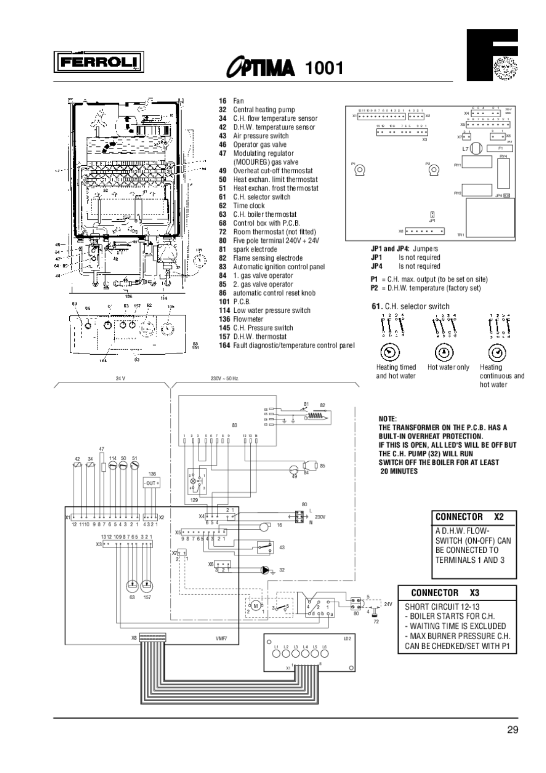
Optima Company 1001 installation instructions Connector

1001 specifications

Optima Company 1001 stands at the forefront of innovation, showcasing a remarkable blend of advanced technology and user-centric design. Founded with the vision of revolutionizing the industry, Optima has quickly positioned itself as a leader in producing high-performance solutions that cater to a diverse clientele.

One of the main features of Optima Company 1001 is its commitment to sustainability. The company has integrated eco-friendly practices into its manufacturing processes, allowing for reduced waste and lower energy consumption. This not only benefits the environment but also enhances the overall efficiency of its products. By utilizing recyclable materials and implementing sustainable sourcing practices, Optima ensures that it remains at the cutting edge of corporate responsibility.

Another hallmark of Optima Company 1001 is its dedication to technological advancement. The firm employs state-of-the-art technologies that resonate with the demands of modern consumers. This includes the use of artificial intelligence and machine learning to optimize operational efficiency and personalize user experiences. Through data analytics, Optima is able to anticipate trends and adapt its offerings, ensuring that customers always receive the most relevant solutions.

Durability and reliability are pivotal characteristics of products manufactured by Optima Company 1001. Each product undergoes rigorous testing to meet high standards of quality and performance. This commitment to excellence means that customers can trust in the longevity and functionality of the products they purchase, giving them peace of mind in their investment.

User-friendliness is also a defining trait of Optima’s offerings. The company places great emphasis on design, ensuring that products are intuitive and accessible to users. This focus on usability is reflected in straightforward interfaces and ergonomic designs that enhance the overall user experience.

Furthermore, Optima Company 1001 prioritizes customer service, providing comprehensive support throughout the product lifecycle. This includes installation assistance, maintenance services, and a robust warranty program, underscoring the company’s dedication to customer satisfaction.

In summary, Optima Company 1001 is characterized by its innovative technologies, commitment to sustainability, product reliability, user-centric design, and exemplary customer service. These features collectively enhance its reputation as an industry leader and pioneer in delivering solutions that are not only high-quality but also aligned with the needs and values of today’s consumers.