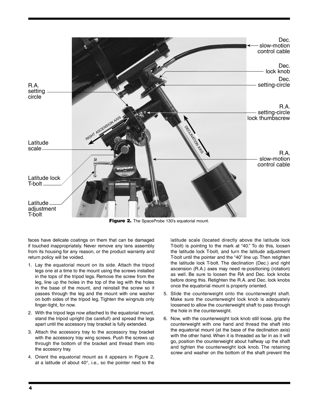
R.A. setting circle
Latitude scale
Latitude lock
Latitude adjustment
|
|
|
| is |
|
| x | ||
|
| a |
| |
|
| ascension |
| |
| t |
| ||
h |
|
|
| |
ig |
|
|
| |
R |
|
|
| |
|
|
|
|
|
Dec. ![]() slow‑motion control cable
slow‑motion control cable
Dec. lock knob
Dec. setting‑circle
R.A. setting‑circle lock thumbscrew
D
eclination
is x a
R.A. slow‑motion control cable
Figure 2. The SpaceProbe 130’s equatorial mount.
faces have delicate coatings on them that can be damaged if touched inappropriately. Never remove any lens assembly from its housing for any reason, or the product warranty and return policy will be voided.
1.Lay the equatorial mount on its side. Attach the tripod legs one at a time to the mount using the screws installed in the tops of the tripod legs. Remove the screw from the leg, line up the holes in the top of the leg with the holes in the base of the mount, and reinstall the screw so it passes through the leg and the mount with one washer on both sides of the tripod leg. Tighten the wingnuts only
2.With the tripod legs now attached to the equatorial mount, stand the tripod upright (be careful!) and spread the legs apart until the accessory tray bracket is fully extended.
3.Attach the accessory tray to the accessory tray bracket with the accessory tray wing screws. Push the screws up through the bottom of the bracket and thread them into the accesory tray.
4.Orient the equatorial mount as it appears in Figure 2, at a latitude of about 40°, i.e., so the pointer next to the
latitude scale (located directly above the latitude lock
5.Slide the counterweight onto the counterweight shaft. Make sure the counterweight lock knob is adequately loosened to allow the counterweight shaft to pass through the hole in the counterweight.
6.Now, with the counterweight lock knob still loose, grip the counterweight with one hand and thread the shaft into the equatorial mount (at the base of the declination axis) with the other hand. When it is threaded as far in as it will go, position the counterweight about halfway up the shaft and tighten the counterweight lock knob. The retaining screw and washer on the bottom of the shaft prevent the
4