Front and Back Panel Descriptions
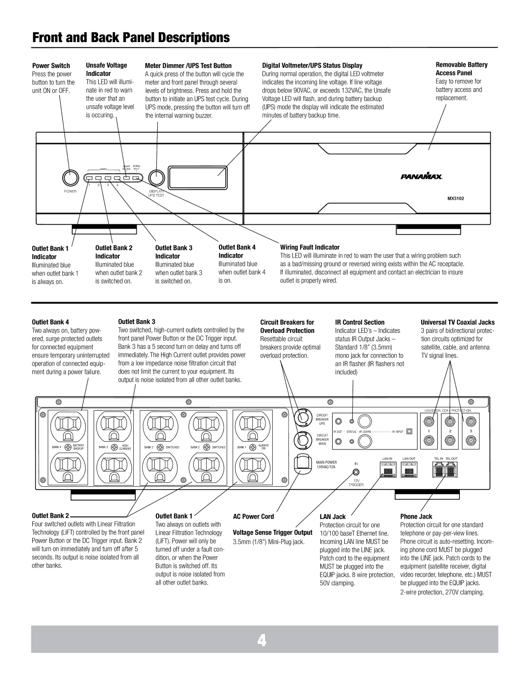
Power Switch Press the power button to turn the unit ON or OFF.
Unsafe Voltage | Meter Dimmer /UPS Test Button |
Indicator | A quick press of the button will cycle the |
This LED will illumi- | meter and front panel through several |
nate in red to warn | levels of brightness. Press and hold the |
the user that an | button to initiate an UPS test cycle. During |
unsafe voltage level | UPS mode, pressing the button will turn off |
is occuring. | the internal warning buzzer. |
Digital Voltmeter/UPS Status Display
During normal operation, the digital LED voltmeter indicates the incoming line voltage. If line voltage drops below 90VAC, or exceeds 132VAC, the Unsafe Voltage LED will flash, and during battery backup (UPS) mode the display will indicate the estimated minutes of battery backup time.
Removable Battery Access Panel Easy to remove for battery access and replacement.
| UNSAFE | WIRING |
BANKS | VOLTAGE | FAULT |
|
|
| O VOLTS IN |
|
|
| EST’D BATTERY: 60 MIN |
1 | 2 | 3 | 4 |
POWER |
|
| DISPLAY/ |
|
|
| UPS TEST |
MX5102 |
Outlet Bank 1 | Outlet Bank 2 | Outlet Bank 3 | Outlet Bank 4 | Wiring Fault Indicator |
Indicator | Indicator | Indicator | Indicator | This LED will illuminate in red to warn the user that a wiring problem such |
Illuminated blue | Illuminated blue | Illuminated blue | Illuminated blue | as a bad/missing ground or reversed wiring exists within the AC receptacle. |
when outlet bank 1 | when outlet bank 2 | when outlet bank 3 | when outlet bank 4 | If illuminated, disconnect all equipment and contact an electrician to insure |
is always on. | is switched on. | is switched on. | is on. | outlet is properly wired. |
Outlet Bank 4
Two always on, battery pow- ered, surge protected outlets for connected equipment ensure temporary uninterrupted operation of connected equip- ment during a power failure.
Outlet Bank 3
Two switched,
Circuit Breakers for | IR Control Section |
Overload Protection | Indicator LED’s – Indicates |
Resettable circuit | status IR Output Jacks – |
breakers provide optimal | Standard 1/8” (3.5mm) |
overload protection. | mono jack for connection to |
| an IR flasher (IR flashers not |
| included) |
Universal TV Coaxial Jacks 3 pairs of bidirectional protec- tion circuits optimized for satellite, cable, and antenna TV signal lines.
|
|
|
|
|
|
|
|
|
| CIRCUIT |
|
|
|
|
|
|
|
|
|
| BREAKER |
|
|
|
|
|
|
|
|
|
| UPS |
|
|
|
|
|
|
|
|
|
| CIRCUIT |
|
|
|
|
|
|
|
|
|
| BREAKER |
BANK 4 | BATTERY | BANK 3 | HIGH | BANK 2 | SWITCHED | BANK 2 | SWITCHED | BANK 1 | ALWAYS | MAIN |
BACKUP | CURRENT | ON |
| |||||||
|
|
|
|
|
|
|
|
IR OUT __ STATUS _ IR LEARN _____________ IR INPUT _ ![]()
UNIVERSAL COAX PROTECTION
|
|
|
|
|
|
|
|
|
|
|
|
|
|
|
|
|
|
|
|
|
|
|
|
|
|
|
|
|
|
|
|
|
| 1 |
|
| 2 |
|
| 3 |
| ||
|
|
|
|
|
|
|
|
|
|
|
|
|
|
|
|
|
|
|
|
|
|
|
|
|
|
|
|
|
|
|
|
|
|
|
|
|
|
|
|
|
|
|
|
LAN IN | LAN OUT | TEL IN TEL OUT |
MAIN POWER | IN |
120VAC/12A |
|
12V
TRIGGER
Outlet Bank 2
Four switched outlets with Linear Filtration Technology (LiFT) controlled by the front panel Power Button or the DC Trigger input. Bank 2 will turn on immediately and turn off after 5 seconds. Its output is noise isolated from all other banks.
Outlet Bank 1
Two always on outlets with Linear Filtration Technology (LiFT). Power will only be turned off under a fault con- dition, or when the Power Button is switched off. Its output is noise isolated from all other outlet banks.
AC Power Cord
Voltage Sense Trigger Output
3.5mm (1/8”)
LAN Jack
Protection circuit for one 10/100 baseT Ethernet line. Incoming LAN line MUST be plugged into the LINE jack. Patch cord to the equipment MUST be plugged into the EQUIP jacks. 8 wire protection, 50V clamping.
Phone Jack
Protection circuit for one standard telephone or
4