Internal encoder adjustments
In order to ensure
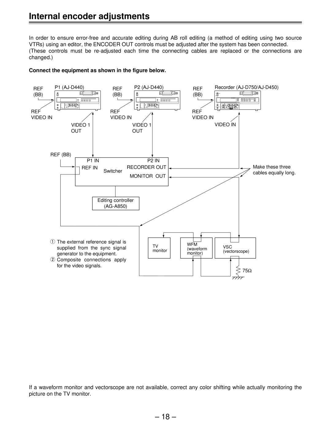
Connect the equipment as shown in the figure below.
REF | P1 | REF | P2 | REF | Recorder |
(BB) |
| (BB) |
| (BB) |
|
REF |
| REF |
| REF |
|
VIDEO IN | VIDEO IN | VIDEO IN |
| ||
| VIDEO 1 |
| VIDEO 1 |
| VIDEO IN |
| OUT |
| OUT |
|
|
| REF (BB) |
|
|
|
|
| P1 IN |
| P2 IN |
|
|
| REF IN | Switcher | RECORDER OUT |
| Make these three |
|
| MONITOR OUT |
| cables equally long. | |
|
|
|
| ||
|
|
|
|
| |
| Editing controller |
|
| ||
|
|
|
| ||
qThe external reference signal is
supplied from the sync signal generator to the equipment.
wComposite connections apply for the video signals.
TV | WFM | VSC | |
(waveform | |||
monitor | (vectorscope) | ||
monitor) | |||
|
|
75Ω
If a waveform monitor and vectorscope are not available, correct any color shifting while actually monitoring the picture on the TV monitor.
– 18 –