Setup menus
USER menu | <TIME CODE> | |
|
|
|
No./Item |
| Description |
|
| |
|
| |
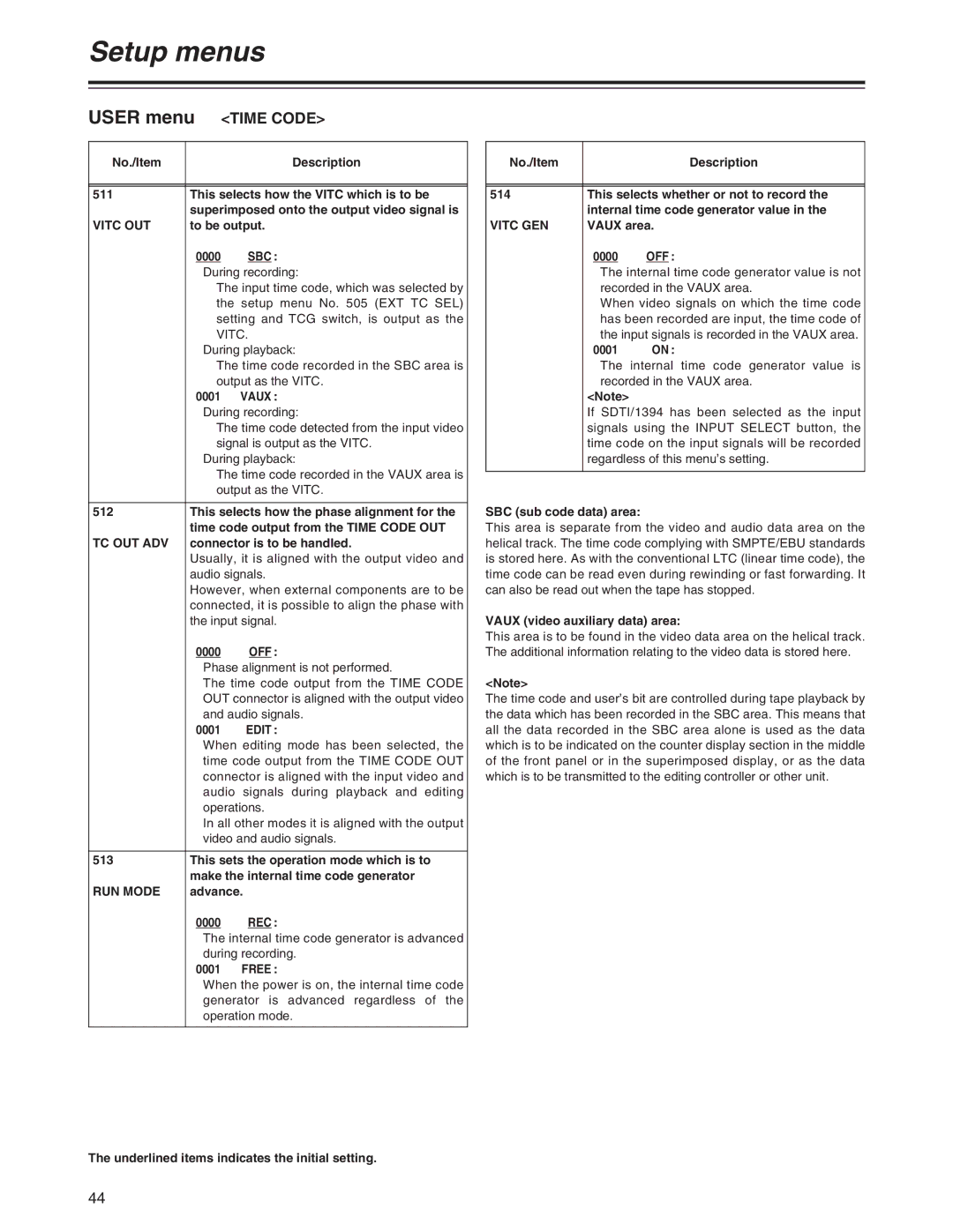
511 | This selects how the VITC which is to be | |
| superimposed onto the output video signal is | |
VITC OUT | to be output. | |
| 0000 | SBC : |
| During recording: | |
| The input time code, which was selected by | |
| the setup menu No. 505 (EXT TC SEL) | |
| setting and TCG switch, is output as the | |
| VITC. | |
| During playback: | |
| The time code recorded in the SBC area is | |
| output as the VITC. | |
| 0001 | VAUX : |
| During recording: | |
| The time code detected from the input video | |
| signal is output as the VITC. | |
| During playback: | |
| The time code recorded in the VAUX area is | |
| output as the VITC. | |
|
| |
512 | This selects how the phase alignment for the | |
| time code output from the TIME CODE OUT | |
TC OUT ADV | connector is to be handled. | |
| Usually, it is aligned with the output video and | |
| audio signals. | |
| However, when external components are to be | |
| connected, it is possible to align the phase with | |
| the input signal. | |
| 0000 | OFF : |
| Phase alignment is not performed. | |
| The time code output from the TIME CODE | |
| OUT connector is aligned with the output video | |
| and audio signals. | |
| 0001 | EDIT : |
| When editing mode has been selected, the | |
| time code output from the TIME CODE OUT | |
| connector is aligned with the input video and | |
| audio signals during playback and editing | |
| operations. | |
| In all other modes it is aligned with the output | |
| video and audio signals. | |
|
| |
513 | This sets the operation mode which is to | |
| make the internal time code generator | |
RUN MODE | advance. | |
| 0000 | REC : |
| The internal time code generator is advanced | |
| during recording. | |
| 0001 | FREE : |
| When the power is on, the internal time code | |
| generator is advanced regardless of the | |
| operation mode. | |
|
|
|
The underlined items indicates the initial setting.
No./Item |
| Description |
|
| |
|
| |
514 | This selects whether or not to record the | |
| internal time code generator value in the | |
VITC GEN | VAUX area. | |
| 0000 | OFF : |
| The internal time code generator value is not | |
| recorded in the VAUX area. | |
| When video signals on which the time code | |
| has been recorded are input, the time code of | |
| the input signals is recorded in the VAUX area. | |
| 0001 | ON : |
| The internal time code generator value is | |
| recorded in the VAUX area. | |
| <Note> |
|
| If SDTI/1394 has been selected as the input | |
| signals using the INPUT SELECT button, the | |
| time code on the input signals will be recorded | |
| regardless of this menu’s setting. | |
|
|
|
SBC (sub code data) area:
This area is separate from the video and audio data area on the helical track. The time code complying with SMPTE/EBU standards is stored here. As with the conventional LTC (linear time code), the time code can be read even during rewinding or fast forwarding. It can also be read out when the tape has stopped.
VAUX (video auxiliary data) area:
This area is to be found in the video data area on the helical track. The additional information relating to the video data is stored here.
<Note>
The time code and user’s bit are controlled during tape playback by the data which has been recorded in the SBC area. This means that all the data recorded in the SBC area alone is used as the data which is to be indicated on the counter display section in the middle of the front panel or in the superimposed display, or as the data which is to be transmitted to the editing controller or other unit.
44
