Setup menus
USER menu | <AUDIO> | |
|
|
|
No./Item |
| Description |
|
| |
|
| |
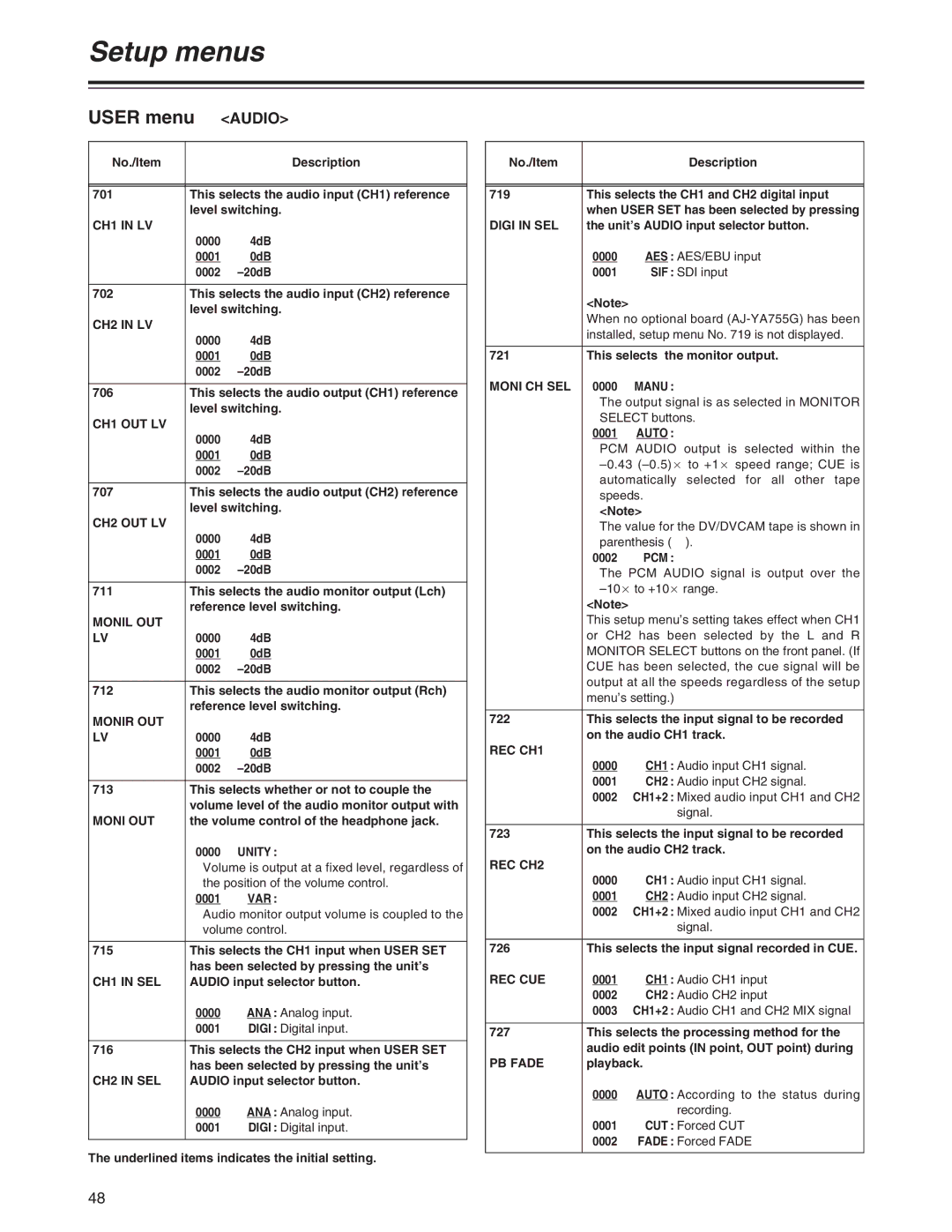
701 | This selects the audio input (CH1) reference | |
| level switching. | |
CH1 IN LV |
|
|
| 0000 | 4dB |
| 0001 | 0dB |
| 0002 | |
|
| |
702 | This selects the audio input (CH2) reference | |
| level switching. | |
CH2 IN LV |
|
|
| 0000 | 4dB |
| 0001 | 0dB |
| 0002 | |
|
| |
706 | This selects the audio output (CH1) reference | |
| level switching. | |
CH1 OUT LV |
|
|
| 0000 | 4dB |
| 0001 | 0dB |
| 0002 | |
|
| |
707 | This selects the audio output (CH2) reference | |
| level switching. | |
CH2 OUT LV |
|
|
| 0000 | 4dB |
| 0001 | 0dB |
| 0002 | |
|
| |
711 | This selects the audio monitor output (Lch) | |
| reference level switching. | |
MONIL OUT |
|
|
LV | 0000 | 4dB |
| 0001 | 0dB |
| 0002 | |
|
| |
712 | This selects the audio monitor output (Rch) | |
| reference level switching. | |
MONIR OUT |
|
|
LV | 0000 | 4dB |
| 0001 | 0dB |
| 0002 | |
|
| |
713 | This selects whether or not to couple the | |
| volume level of the audio monitor output with | |
MONI OUT | the volume control of the headphone jack. | |
| 0000 | UNITY : |
| Volume is output at a fixed level, regardless of | |
| the position of the volume control. | |
| 0001 | VAR : |
| Audio monitor output volume is coupled to the | |
| volume control. | |
|
| |
715 | This selects the CH1 input when USER SET | |
| has been selected by pressing the unit’s | |
CH1 IN SEL | AUDIO input selector button. | |
| 0000 | ANA : Analog input. |
| 0001 | DIGI : Digital input. |
|
| |
716 | This selects the CH2 input when USER SET | |
| has been selected by pressing the unit’s | |
CH2 IN SEL | AUDIO input selector button. | |
| 0000 | ANA : Analog input. |
| 0001 | DIGI : Digital input. |
|
|
|
The underlined items indicates the initial setting.
No./Item |
| Description |
|
| |
|
| |
719 | This selects the CH1 and CH2 digital input | |
| when USER SET has been selected by pressing | |
DIGI IN SEL | the unit’s AUDIO input selector button. | |
| 0000 | AES : AES/EBU input |
| 0001 | SIF : SDI input |
| <Note> |
|
| When no optional board | |
| installed, setup menu No. 719 is not displayed. | |
|
| |
721 | This selects the monitor output. | |
MONI CH SEL | 0000 | MANU : |
| The output signal is as selected in MONITOR | |
| SELECT buttons. | |
| 0001 | AUTO : |
| PCM AUDIO output is selected within the | |
| ||
| automatically selected for all other tape | |
| speeds. | |
| <Note> | |
| The value for the DV/DVCAM tape is shown in | |
| parenthesis ( ). | |
| 0002 | PCM : |
| The PCM AUDIO signal is output over the | |
| ||
| <Note> |
|
| This setup menu’s setting takes effect when CH1 | |
| or CH2 has been selected by the L and R | |
| MONITOR SELECT buttons on the front panel. (If | |
| CUE has been selected, the cue signal will be | |
| output at all the speeds regardless of the setup | |
| menu’s setting.) | |
|
| |
722 | This selects the input signal to be recorded | |
| on the audio CH1 track. | |
REC CH1 |
|
|
| 0000 | CH1 : Audio input CH1 signal. |
| 0001 | CH2 : Audio input CH2 signal. |
| 0002 | CH1+2 : Mixed audio input CH1 and CH2 |
|
| signal. |
|
| |
723 | This selects the input signal to be recorded | |
| on the audio CH2 track. | |
REC CH2 |
|
|
| 0000 | CH1 : Audio input CH1 signal. |
| 0001 | CH2 : Audio input CH2 signal. |
| 0002 | CH1+2 : Mixed audio input CH1 and CH2 |
|
| signal. |
|
| |
726 | This selects the input signal recorded in CUE. | |
REC CUE | 0001 | CH1 : Audio CH1 input |
| 0002 | CH2 : Audio CH2 input |
| 0003 | CH1+2 : Audio CH1 and CH2 MIX signal |
|
| |
727 | This selects the processing method for the | |
| audio edit points (IN point, OUT point) during | |
PB FADE | playback. | |
| 0000 | AUTO : According to the status during |
|
| recording. |
| 0001 | CUT : Forced CUT |
| 0002 | FADE : Forced FADE |
|
|
|
48