Operating Instructions
For Your Safety Please Read the Following Text Carefully
Safety precautions
How to replace the fuse
For Your Safety Please Read the Following Text Carefully
For business users in the European Union
Contents
System settings
Input/output signal settings
Description
Features
Precautions for use
Functions in each area
Power indicator Power
2Alarm indicator Alarm
System/Alarm 8/16
Crosspoint area
Wipe area
= User buttons User 1, User
User button area
Transition area
PinP button
Auto button
CUT button
FTB button
List of menu delegation functions
LCD menu area
Rotary encoders F1 to F5
Positioner Rotary encoder Valid menu
Positioner area
Positioner X/Y
Rotary encoder Z
Concerning the recommended SD memory cards
SD memory card access LED
SD memory card area
PSD memory card slot
External synchronization mode
SDI signal input connectors SDI Inputs 1 to
SDI signal output connectors SDI Outputs PGM, 1
Reference input connector/BB output connector REF
AC power input socket in AC 220 V to 240
Tally output connector Tally D-sub 15-pin, male, inch screw
\ GPI input connector GPI 3.5 mm diameter stereo mini jack
Ground connector
Table of optional boards
Configuration
Where connected
System
AV-HS400AE
Connections
Example where the optional board is used
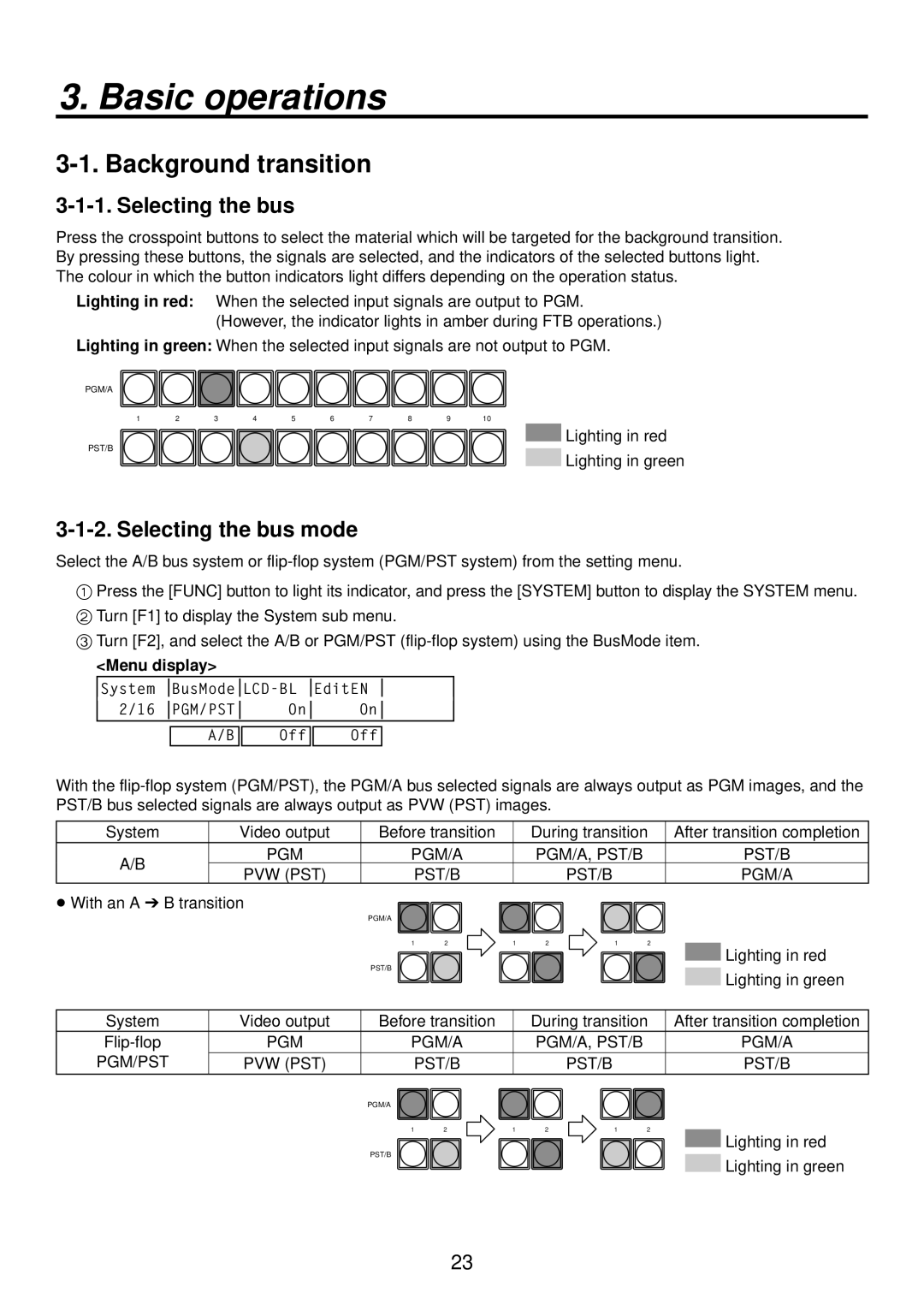
Selecting the bus
Selecting the bus mode
Basic operations
Background transition
Cut transition
Selecting the transition mode
Manual transition using the fader lever
Auto transition
Table of wipe patterns
How to select the wipe patterns
Wipe
Selecting the wipe pattern
Selecting the wipe direction
Setting the border and soft effect
Setting the border colour
To call the preset colour
Pos, Y-Pos setting range
Setting the wipe start position
Modifying wipe
Setting the lighting effect
Setting the trimming
Key source
Key
Key, PinP and DSK priorities
How key composition works Background
Chroma chroma key/self key
Selecting the key type
Lum luminance key/self key
Linear linear key/EXT key
Setting the fill matte colour
Selecting the key fill and key source signals
Selecting the key fill signal
Selecting the key source signal
Pattern examples
Key transitions
Key preview
Adjusting the luminance key and linear key
Operation Parameter Description of setting Setting range
Rotary encoder Z
Adjusting the chroma key
Executing auto sampling
Positioner
Item operations
Adjusting the chroma key
Tips for chroma key adjustments
Making other adjustments
Key decorations
Setting the key edge
Setting the edge colour
Turn F2 to F5 to set the area to be masked
Masking the key signals
Flying key
PinP combinations using the flying key
PinP preview
PinP picture in picture
Selecting the PinP material
PinP transitions
Adjusting the density
PinP adjustments
Adjusting the PinP position and size
Select the dot by dot mode
PinP decorations
Trimming settings
Selecting the DSK type
DSK downstream key
Selecting the DSK material
Selecting the DSK fill signal and DSK source signal
Selecting the DSK fill signal
Selecting the DSK source signal
DSK preview
DSK adjustments
DSK transitions
DSK decorations
Setting the edge
Masking the DSK signals
FTB fade to black
Calling the preset colours
Internal colour signals
Setting the colour background
Adjusting the colours
Displaying the freeze status
Freezing the input signals
Setting freeze
Selecting the output signals using the crosspoint buttons
Switching the AUX output
Border Bkgd Wipe
Preset memory
Table of stored preset memory
Transition area
Color
Description of setting Initial value factory default Key
Chroma key
Clear This is used to clear contents in the preset memory
Transferring images from the AUX bus
Frame memories
SD memory cards
Initializing the SD memory cards
Saving data on SD memory cards
Characters which can be used for filenames
Loading data from SD memory cards
Displaying the SD memory card information
Deleting files on SD memory cards
Setting the frame synchronizer
Input/output signal settings
Setting the SDI input signals and analogue input signals
576/50i 1080/59.94i
Setting the input mode
System Mode Input
List of input modes supported
Setting the analogue composite input signals
Setting the analogue input gain
Input image
Setting the up-converter option
Automatic adjustment of the white level
Setting the DVI input signals option
Setting the DVI input signals
Automatic adjustment of the black level
Fit-H
1280 720
Fit-V
1024 768
Adjusting the DVI input signals
Connector Signal type Output default Assignment
Setting the output signals
Types of output signals
DC down-converter
Assigning the output signals
Normal
Setting the sync signals
Phase Video format Adjustment range
Adjusting the output signal phase
Output video signal phase adjustment
System standard 1H Output +1H Shortest Output +0.5H
Phase adjustment setup
Frame synchronizer
Signals
Video effects Output signals Down-converter
When the 1080/59.94i format is used
For 1080/59.94i format Example
Phase relationship between input signals and output signals
Display modes Division mode
Setting the multi view display
Setting the screen layout
These can be set to PGM, PVW, AUX or KeyOut
Upper-L, Upper-R
LUM 0%, 25%, 50%, 75%, 100%
Setting the split frame and characters
Setting the tally displays
Changing the material names
Preset type setting procedure
User type setting procedure
Examples of OSD displays
Setting the on-screen display OSD
Setting the DVI output signals option
Setting the embedded audio data
Setting the ancillary data
Setting the V ancillary data
LB letter box
Setting the down-converter
SQ squeeze
EC edge crop
Selecting the video format
System settings
Setting the 169 squeeze mode
Button Signal Abbreviation Description
Setting the crosspoints
Assigning signals to the crosspoints
Assigning signals to the crosspoints
Button Signal Description
Setting the crosspoint switching
Button assignments
Setting the user buttons
Setting the FTB button
Setting method
Setting the time
Setting the date and time
Setting the date
Setting the gateway
Network settings
Setting the IP address
Setting the subnet mask
Setting the protocol
Other settings
Setting the LCD backlight
Setting editor enable
Setting the GPI
Functions that can be controlled from the unit
Camera control
RS-422RS-232C Converter
Connection specifications
AW-RP655L RS-422 RS-232C Converter
Pin No
Connections for AW-HE100N/E, AW-PH405E or AW-PH360L
AW-HE100N/E, AW-PH405E, AW-PH360L Pin No Signal
AW-PH400E
AW-IF400G Switch settings
Connections for AW-PH400E
For controlling the lens zooming
Camera control settings
System settings
Status displays
Alarm status displays
OUT-SL1, 2 option output slots 1
Displaying the version information and option information
Control, Panel, Input, M/E
IN-SL1, 2 option input slots 1
Initialization
External interfaces
RS-422 connector
Function assigned Description of control Remarks
GPI connector
Initial setting
Control functions that can be assigned
Example of tally connections
Pin No Signal name Input/output Description of signal
LAN straight cable
Specifications
Image transmission functions
Connections
How to install the software
Exit
Setting the IP address
Operation
Startup
Transmitting images to the unit
Transmitting images from the unit
Parameter
Setting menu table
Hue-Rad Sat-Rad Soft Cancel
Adjust
Adjust1
Adjust2
Trim Manual
Border Width Soft Mode
Type Fill
Position
System Phase
Signal Mode ↓ AnaGain
Signal Output Mode ↓
Sync ↓ BBSetup GenLock
Signal Scale ↓ Delay ↓ Sharp ↓
Signal Mode ↓ Size ↓ Scale ↓
Signal Scale ↓ MovDet ↓ Sharp ↓
Signal Chroma Ped Hue
Power Fan
Mode ↓ 169SQ
Signal PosCont Speed Power ↓
Alarm
Hour Minute Second Set ↓
Date
Year Month Date Set ↓
Time
Unit mm
Appearance
Specifications and standard accessories
Composite input
Video delay time
SDI outputs
Analogue
Optional boards sold separately
Standard accessories
Appendix glossary
Genlock
Frame Memory
Freeze
FTB Fade to Black
Programme Bus
Preset Bus
Preset Memory
Preview
Panasonic Corporation