E N G L I S H
Electrical Connections
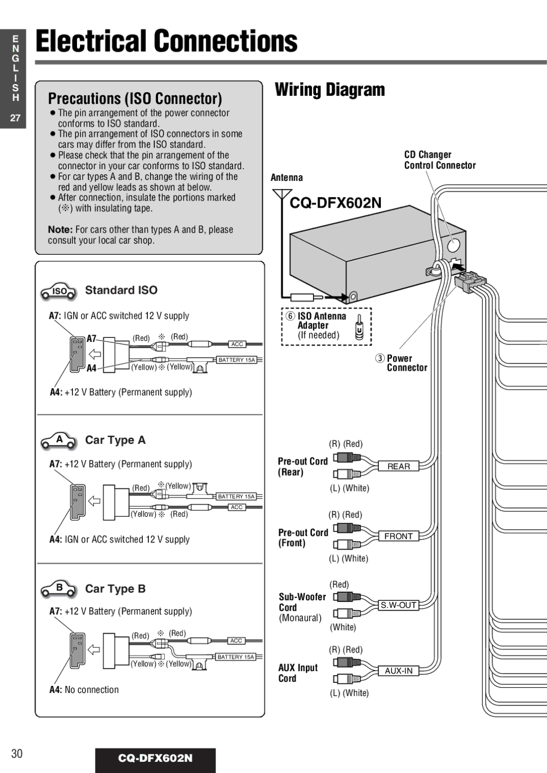
Precautions (ISO Connector) | Wiring Diagram |
|
27¡The pin arrangement of the power connector conforms to ISO standard.
¡The pin arrangement of ISO connectors in some cars may differ from the ISO standard.
¡Please check that the pin arrangement of the connector in your car conforms to ISO standard.
¡For car types A and B, change the wiring of the red and yellow leads as shown at below.
¡After connection, insulate the portions marked (C) with insulating tape.
Note: For cars other than types A and B, please consult your local car shop.
CD Changer
Control Connector
Antenna
CQ-DFX602N
ISO | Standard ISO |
|
| |
A7: IGN or ACC switched 12 V supply | y ISO Antenna | |||
|
|
|
| Adapter |
| A7 | (Red) | C (Red) | (If needed) |
|
|
| ACC |
|
|
|
| BATTERY 15A | e Power |
| A4 | (Yellow) C(Yellow) | Connector | |
A4: +12 V Battery (Permanent supply)
A | Car Type A | (R) (Red) |
|
|
A7: +12 V Battery (Permanent supply)
(Red) | C(Yellow) |
| BATTERY 15A |
| ACC |
(Yellow) C (Red) | |
A4: IGN or ACC switched 12 V supply
BCar Type B
A7: +12 V Battery (Permanent supply)
![]() (Red) C (Red)
(Red) C (Red)
ACC |
BATTERY 15A |
(Yellow) C(Yellow) |
A4: No connection
(L) (White)
(R) (Red)
(L) (White)
(Red)
(White)
(R) (Red)
AUX Input
Cord
(L) (White)
REAR
FRONT
![]()