Editing
Assemble Editing
The assemble editing function makes it easy to record the picture and sound of virtually any number of scenes or programmes in succession.
Assemble editing from an external source, for example from a video movie camera, can be performed in the same way.
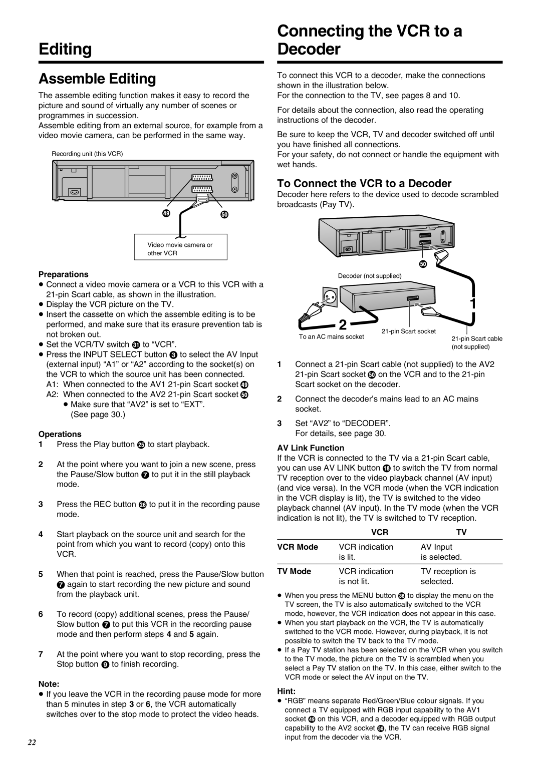
Recording unit (this VCR)
a b
Video movie camera or other VCR
Preparations
≥Connect a video movie camera or a VCR to this VCR with a
≥Display the VCR picture on the TV.
≥Insert the cassette on which the assemble editing is to be performed, and make sure that its erasure prevention tab is not broken out.
≥Set the VCR/TV switch O to “VCR”.
≥Press the INPUT SELECT button 3 to select the AV Input (external input) “A1” or “A2” according to the socket(s) on the VCR to which the source unit has been connected.
A1: When connected to the AV1
A2: When connected to the AV2
≥Make sure that “AV2” is set to “EXT”. (See page 30.)
Operations
1Press the Play button I to start playback.
2At the point where you want to join a new scene, press the Pause/Slow button 7 to put it in the still playback mode.
3Press the REC button J to put it in the recording pause mode.
4Start playback on the source unit and search for the point from which you want to record (copy) onto this VCR.
5When that point is reached, press the Pause/Slow button 7 again to start recording the new picture and sound from the playback unit.
6To record (copy) additional scenes, press the Pause/ Slow button 7 to put this VCR in the recording pause mode and then perform steps 4 and 5 again.
7At the point where you want to stop recording, press the Stop button 9 to finish recording.
Note:
≥If you leave the VCR in the recording pause mode for more than 5 minutes in step 3 or 6, the VCR automatically switches over to the stop mode to protect the video heads.
22
Connecting the VCR to a Decoder
To connect this VCR to a decoder, make the connections shown in the illustration below.
For the connection to the TV, see pages 8 and 10.
For details about the connection, also read the operating instructions of the decoder.
Be sure to keep the VCR, TV and decoder switched off until you have finished all connections.
For your safety, do not connect or handle the equipment with wet hands.
To Connect the VCR to a Decoder
Decoder here refers to the device used to decode scrambled broadcasts (Pay TV).
b ![]()
Decoder (not supplied)
| 1 | |
2 | ||
To an AC mains socket | ||
| ||
| (not supplied) |
1Connect a
2Connect the decoder’s mains lead to an AC mains socket.
3Set “AV2” to “DECODER”. For details, see page 30.
AV Link Function
If the VCR is connected to the TV via a
| VCR | TV |
VCR Mode | VCR indication | AV Input |
| is lit. | is selected. |
|
|
|
TV Mode | VCR indication | TV reception is |
| is not lit. | selected. |
≥When you press the MENU button T to display the menu on the TV screen, the TV is also automatically switched to the VCR mode, however, the VCR indication does not appear in this case.
≥When you start playback on the VCR, the TV is automatically switched to the VCR mode. However, during playback, it is not possible to switch the TV back to the TV mode.
≥If a Pay TV station has been selected on the VCR when you switch to the TV mode, the picture on the TV is scrambled when you select a Pay TV station on the TV. In this case, either switch to the VCR mode or select the AV input on the TV.
Hint:
≥“RGB” means separate Red/Green/Blue colour signals. If you connect a TV equipped with RGB input capability to the AV1 socket a on this VCR, and a decoder equipped with RGB output capability to the AV2 socket b, the TV can receive RGB signal input from the decoder via the VCR.