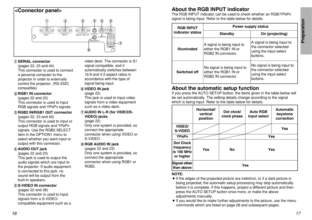
<Connector panel>
# $ % & ' (
![]()
![]()
![]() )
)
*
About the RGB INPUT indicator
The RGB INPUT indicator can be used to check whether an RGB/YPBPR signal is being input. Refer to the table below for details.
RGB INPUT | Power supply status | ||
|
| ||
indicator status | Standby | On (projecting) | |
| |||
|
|
| |
| A signal is being input to | A signal is being input to | |
| the connector selected | ||
Illuminated | either the RGB1 IN or | ||
using the input select | |||
| RGB2 IN connector. | ||
| buttons. | ||
|
| ||
Preparation
#SERIAL connector (pages 22, 23 and 44)
This connector is used to connect a personal computer to the projector in order to externally control the projector.
$RGB1 IN connector (pages 22 and 23)
This connector is used to input RGB signals and YPBPR signals.
%RGB2 IN/RGB1 OUT connector (pages 22, 23 and 40)
This connector is used to input or output RGB signals and YPBPR signals. Use the RGB2 SELECT item in the OPTION1 menu to select whether you want input or output with this connector.
&AUDIO OUT jack (pages 22 and 23)
This jack is used to output the audio signals which are input to the projector. If audio equipment is connected to this jack, no sound will be output from the
'S-VIDEO IN connector (pages 22 and 38)
This connector is used to input signals from a
video deck. The connector is S1 signal compatible, and it automatically switches between 16:9 and 4:3 aspect ratios in accordance with the type of signal being input.
(VIDEO IN jack (page 22)
This jack is used to input video signals from a video equipment such as a video deck.
)AUDIO IN L-R (for VIDEO/S- VIDEO) jacks
(page 22)
Only one system is provided, so connect the appropriate connector when using VIDEO or
*RGB AUDIO IN jack (pages 22 and 23)
Only one system is provided, so connect the appropriate connector when using RGB1 or RGB2.
No signal is being input to | No signal is being input to | |
the connector selected | ||
Switched off either the RGB1 IN or | ||
using the input select | ||
RGB2 IN connector. | ||
buttons. | ||
|
About the automatic setup function
If you press the AUTO SETUP button, the items given in the table below will be set automatically. The setting details change according to the signal which is being input. Refer to the table below for details.
| Horizontal/ | Dot clock/ | Auto RGB |
| Automatic |
| vertical |
| keystone | ||
| clock phase | input select |
| ||
| position |
| correction | ||
|
|
|
| ||
|
|
|
|
|
|
VIDEO/ |
|
|
|
| Yes |
|
|
|
|
| |
|
|
|
|
| |
|
|
|
|
|
|
YPBPR |
|
| Yes |
| |
|
|
|
|
|
|
Dot Clock |
|
|
|
|
|
frequency | Yes | No | Yes |
| |
is 100 MHz |
| ||||
|
|
|
|
| |
or higher |
|
|
|
|
|
|
|
|
|
|
|
Signal other |
| Yes |
| ||
than above |
|
| |||
|
|
|
|
| |
|
|
|
|
|
|
NOTE:
BIf the edges of the projected picture are indistinct, or if a dark picture is being projected, the automatic setup processing may stop automatically before it is complete. If this happens, project a different picture and then press the AUTO SETUP button once more, or make the above adjustments manually.
BIf you would like to make further adjustments to the picture, use the menu commands which are listed on page 28 and subsequent pages.
16 | 17 |
