Introduction and Installation
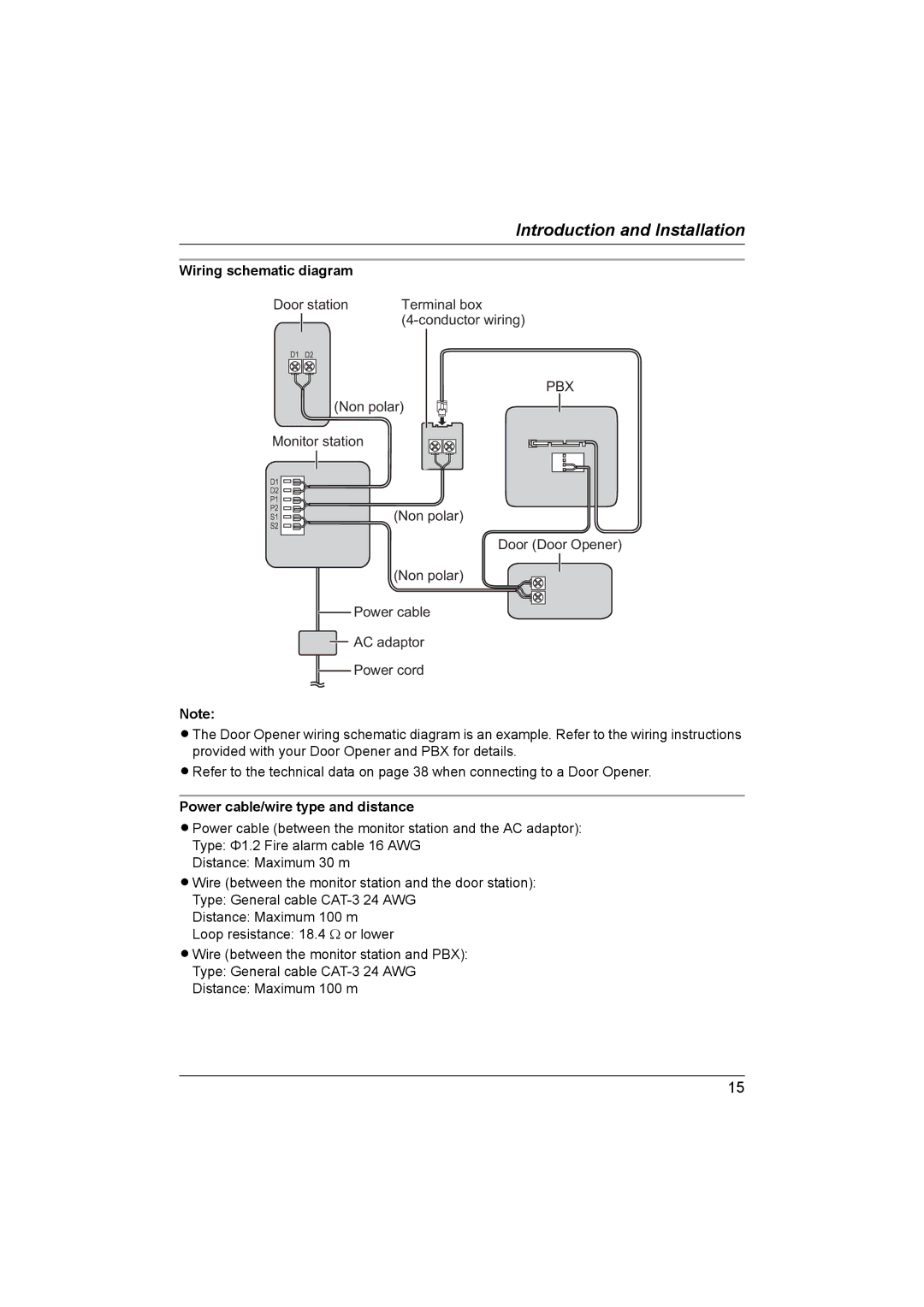
Wiring schematic diagram |
| |
Door station | Terminal box | |
|
| |
|
|
|
D1 D2
(Non polar)
PBX
Monitor station
D1 |
|
D2 |
|
P1 |
|
P2 | (Non polar) |
S1 | |
S2 |
|
Door (Door Opener)
(Non polar)
![]() Power cable
Power cable
![]() AC adaptor
AC adaptor
![]() Power cord
Power cord
Note:
LThe Door Opener wiring schematic diagram is an example. Refer to the wiring instructions provided with your Door Opener and PBX for details.
LRefer to the technical data on page 38 when connecting to a Door Opener.
Power cable/wire type and distance
LPower cable (between the monitor station and the AC adaptor):
Type: Ф1.2 Fire alarm cable 16 AWG
Distance: Maximum 30 m
LWire (between the monitor station and the door station):
Type: General cable
Distance: Maximum 100 m
Loop resistance: 18.4 Ω or lower
LWire (between the monitor station and PBX):
Type: General cable
Distance: Maximum 100 m
15