WJ-HD309
English Version
Important Safety Instructions
Contents
Features
Preface
Precautions
Trademarks and Registered Trademarks
Limitation of Liability
WJ-HD309
Front View
WJ-HD316
4Preset, Auto Pan Button PRESET/AUTO
@0Setup, Escape Button SETUP/ESC
@1Busy Indicator Busy
@6Connectors Cover @7Copy Port COPY2
Rear View
WJ-HD316 WJ-HD309
On the Monitor 1 To display only live image
Mode
On the Monitor 2 To display live or recorded image
Task Bar
Indicated Item Status Indication
Status on the Task Bar
On the Main Bar
Abbreviation of partition
On the Left Bar
On the Right Bar
Played on the monitor
Second from the bottom 40 % of the disk space
Enter a user name and password
Password
Startup
Display a live image
Clock Adjustment
Press the SETUP/ESC button for 2 seconds or more
Time & Date menu will be displayed
Selected date format and the set time will be applied
Shutdown
Recording Mode and Priority
Recording Mode Description Priority*1
Start recording
Stop recording
Recording Time
Recording with audio
Recording without audio
EXA NQA FQA SFA
Press the external switch
Recording duration of emergency recording
Parameter Recording Duration
Manual
Playback
Available functions during playback
Start playback
Stop playback
100x
To play at normal speed, release the shuttle ring
Shuttle ring is released
Skip
Marking For the WJ-HD316 For the WJ-HD309
Repeatedly
Designate a start point a by pressing the a B Repeat button
During playback
Shift indicator will light
Playback Image on a Designated Disk
Press the Shift button
HDD Normal Recording Area/Event Recording Area
Cv cv
To stop playback, press the Stop button
Press the Stop button
Playback from a Designated Time and Date
Press the PLAY/PAUSE button
Searching Filters
Search and Play
Recording Event List Window
Recording Event Thumbnail Window
List window
Thumbnail window
Filter recording events
Filter recording events by time and date
Filter recording events by camera channel
Filter recording events by recording event
List window Thumbnail window
VMD Search TIME&DATE CAM
Cn xvn cb
Press the SET button
⁄0 m⁄2 ,⁄1
ANY Area mode
Vector mode
⁄5Rotate the jog dial to select a result to be dis- played
⁄6Press the PLAY/PAUSE button to start play- back
Detection Mode
Duration mode
To delete the motion detection area
Selected area will be deleted
Rotate the jog dial to select a desired marked time
TIME&DATE CAM
Monitor Live Images
Displaying Live Images on a Single Screen
Electronic Zoom
Press the MONITOR1/MONITOR2 button to select the monitor
When displaying on a 4-split screen
When displaying on a 9-split screen
Displaying on a Multi-screen
To display on a single screen
Sequential Display
Press the SEQ button
Control Cameras
Panning/Tilting
Zoom
Focus
Preset Action
Register Preset Positions of Cameras
Use the arrows button AB to adjust the iris
Iris
Press the PRESET/AUTO button
Move a camera to the preset position
Select OK using the arrows button and press the SET button
Auto Function Auto Pan, etc
13 14 15
Action at an event occurrence
About the event action mode
About the Event Function
Alarm Function
Blinks the Alarm indicator on the front panel
Moves a camera to the preset position
Starts recording automatically
Cancel the Alarm Action
Suspend the Alarm Actions
To suspend deactivate temporarily the alarm actions
To stop suspending the alarm actions
Copying Duplicate
Press the Copy button
To eject the disk of COPY1
To eject the disk of COPY2
Move the cursor to Data Delete using the arrows button CD
Delete Data on the Disk
Data Delete menu will be displayed
Cursor will be displayed on the Data Delete menu
Confirmation dialog window will be displayed
To not delete, select Cancel
Press the SET button for 2 seconds or more
Format Initialize a DVD-RAM Disk
Press the ESC/SETUP button for 2 seconds or more
Select Data Delete using the arrows button CD
Press the SETUP/ESC button to close the Setup Menu window
Press the SET button to select Format
DISPLAY/EDIT Text Information
Press the Text button again to edit text infor- mation
Press the SET button to apply the edited char- acters
To insert a character
To delete a character
To delete all characters
ERROR/WARNINGS
Error status
Remove
FAN
Operation Using a System Controller
Menu
WV-CU360C
Available only during playback
Available only when displaying live images or a
List, or when pausing playback
Cancel copying
Sequential display on For the WJ-HD316
System Requirements of a PC
Operation Using a PC
Features
Installation in the Rack
Management of USERS/HOSTS
When the unit is operated directly
Setting for Priority Description
OFF
When the unit is operated using a PC via a network
Log in the unit as an adminis Trator
HDD Disk Menu
After completing the settings, press any button to close
Operating the Unit for the First Time
Start maintenance after this window is displayed
Following window will be displayed after around 30 sec- onds
When replacing the built-in hard disk of the unit
When replacing the built-in hard disk of the extension unit
Examples of connections
Connections when the unit is used independently
Connections
Connections with an extension unit
Cable Clamp Fixing screw
Connections with DVD-RAM, CD-R, and DVD-R drives
Designated DVD-RAM drive, etc USB cable Locally procured
Connections with the VCR
Open the terminal cover
Mode switch No on
Connections with PS·Data systems
PS·Data setup of Comm on the Setup Menu
Unit Address System Unit Address Controller
When no PS·Data compatible device is connected to the system
Cascade connection of multiple units
PS·Data Setup
PS · Data Compatible Third unit System 3 Controller
PS · Data application Monitor
Connection with the RS485 camera
Connection
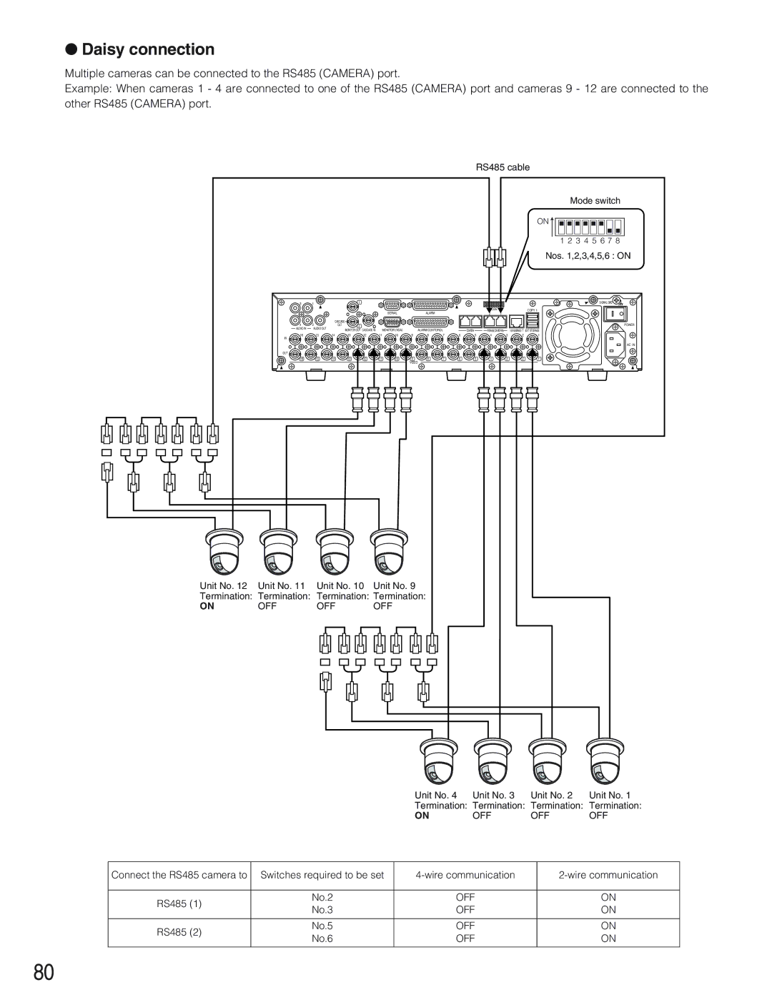
Daisy connection
Nos ,2,3,4,5,6 on
Mode Switch
When connecting RS485 cameras
For 2-wire communication
For 4-wire communication
How to Use the Terminals of the ALARM/CONTROL Connector
Pin array
Connection is correct referring to the following
Pin No Operation Remarks
Connection for external recording changeover
ALARM/CONTOROL
Connection for emergency recording
Connection for the Auto Adjust Time function
Example
Connection with the Uninterruptible Power System UPS
Connection of the control output
How to Use the Terminals of the Alarm Connector
Pin Configuration
Alarm connection
Terminal Active time
How to Use the Serial Connector
Pin Configuration
Connection example
Connection example of cross cable
Terminal Setup Specify the alarm terminal polarity
Setup
Item list of the Setup Menu
Host Delete Delete the registered hosts
Save/Load Set contents can be saved or loaded
User Delete Delete registered users
Live image
About the Setup Menu
Main menu
Basic Operation with the Setup Menu
Screenshot
Maintenance Functions for Maintaining
Hour meter warning setting
HDD safety mode
Disk Info Check the available hard disk space
Auto Delete
Manual Delete for Normal Recording Area
Manual Delete for Event Recording Area
Disc Format of DVD
Indication Description Cause
Error Log Check the error log
Event Log Check the event log
Access Log Check the access log
REC Setup Perform the settings for the basic recording
Recording
Emergency REC Perform the settings for emergency recording
Event Function for Events
Delete the motion detection area Screenshot
Cross cursor will be displayed on the VMD Setup win- dow
100
Set the sensitivity
Set the detection mode
101
About the Detection mode
102
ANY Area to detect motion in the area
Duration to detect objects that keep moving in the area
Alarm Auto Reset
Alarm Disarm
Select how to supply the signal to the alarm terminal
103
Schedule Settings for the recording/event action schedule
Flowchart how to create a schedule
Resolution
Recording Rate for Each Recording Mode
105
Recording Rate and Image Quality for Each Camera Channel
Terminal/command alarm
106
Video Loss
Event Program Create event programs for an event occurrence
Radio button for New Time Table Setup is checked
107
Start operation after displaying the timetable window
Press the SET button
108
Switcher Settings for the switcher function
Monitor 1 Switcher function of monitor
109
Live Sequence
Login Screen
110
Sequence Timing
Auto Skip
Monitor 2 Switcher function of monitor
111
OSD Setup
112
Display
Camera Title
113
Camera Title Display Position
Line Color on the Multi Screen
Time & Date Display Position
Alarm Display
Display Mode
114
Camera Title Display
Comm Settings for communication with other devices
115
Unit Address System
Unit Address Controller
116
RS232C Setup Settings for RS232C
117
Control Camera CH
Unit AddressSystem
118
119
System Settings on System
120
121
Password
Default Screen
122
User Name
123
Camera Partitioning
Host IP Address
Level
User Level Setting of operation level
124
Host Edit Correction of registered host infor- mation
Host Delete Deletion of registered host
Functions that can be enabled/disabled
0Save/Load Saving and loading of settings of the Setup Menu
125
Function Description
Display Setup Menu of Camera
126
127
How to replace the built-in hard disk
Disk Management
128
Remove the cable from the front panel
When replacing the built-in hard disk of the unit
129
Display of the HDD Disk Menu
130
About the HDD Disk Menu
RAID 5 Function of the Extension Unit
Setup/cancel the RAID 5 function
131
Screen displayed when using the RAID 5 function
132
Formatting Initialization the Hard Disk
Formatting initialization all hard disks unit
Formatting initialization the selected hard disk unit
Press the SET button after setting
133
Setting Method menu will be displayed
Screen displayed when selecting Auto Setup
Screen displayed when selecting ALL Copy Area
134
PRE Recording Areas menu will be displayed
Detailed Setup menu will be displayed
135
Setting for Mirroring
Mirror Area Setup menu will be displayed
136
Start mirroring
137
Cancel mirroring Mirror OFF
Hard disk recovery Mirror on
Remove the Hard Disk Logically and Reconfigure it Remove
138
139
WJ-HD300 TOP Menu Removing
Command Format
Following details how to write the commands
Response Command from the Unit to the PC
140
When an Answer command is required
Transmission command → The unit Response command ← The unit
141
Sends back data
Reception Error
Communication error Reception error
Parameter error
142
143
PC Connection Example
Command Table
144
145
OQS0
146
ZCR
147
QSR
148
QRM
149
Flowchart of the Setup Menu
150
Maintenance
151
Schedule
152
Event
Display
Switcher
153
154
Com
155
System
156
YY.MM.DD/MMM.DD.YY/DD.MMM.YY
16SCREEN/SEQ CAM1
LV1,LV2,LV3
Troubleshooting
157
158
Problem
159
160
Check if the network is crowded Refer to p
Specification
161
General
Input/Output
162
CD-ROM
163
NM0104-0 3TR001706AAA