CONNECTIONS
The connections described below should be made by qualified service personnel or system installers.
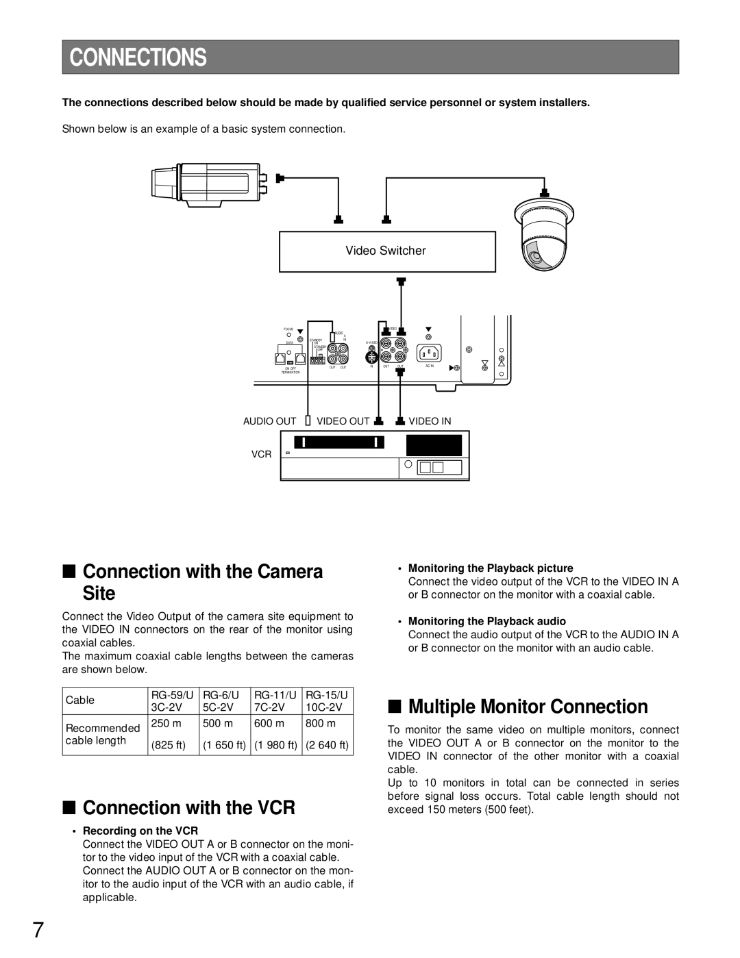
Shown below is an example of a basic system connection.
Video Switcher
FOCUS |
| AUDIO |
| B VIDEO | A |
| |
|
|
| IN | IN |
| ||
|
| B | A |
|
| ||
DATA | STANDBY | IN | IN |
|
|
| |
ON |
|
|
|
|
| ||
| STANDBY |
|
|
|
|
|
|
| OFF |
|
|
|
|
|
|
| G |
|
|
|
|
|
|
ON OFF |
| OUT | OUT | IN | OUT | OUT | AC IN |
|
|
|
|
| |||
TERMINATION |
|
|
|
|
|
|
|
AUDIO OUT VIDEO OUT |
|
|
|
|
|
|
|
|
| VIDEO IN |
VCR
■Connection with the Camera
Site
Connect the Video Output of the camera site equipment to the VIDEO IN connectors on the rear of the monitor using coaxial cables.
The maximum coaxial cable lengths between the cameras are shown below.
Cable | |||||
| |||||
Recommended | 250 m | 500 m | 600 m | 800 m | |
|
|
|
| ||
cable length | (825 ft) | (1 650 ft) | (1 980 ft) | (2 640 ft) | |
| |||||
|
|
|
|
|
■Connection with the VCR
• Recording on the VCR
•Monitoring the Playback picture
Connect the video output of the VCR to the VIDEO IN A or B connector on the monitor with a coaxial cable.
•Monitoring the Playback audio
Connect the audio output of the VCR to the AUDIO IN A or B connector on the monitor with an audio cable.
■Multiple Monitor Connection
To monitor the same video on multiple monitors, connect the VIDEO OUT A or B connector on the monitor to the VIDEO IN connector of the other monitor with a coaxial cable.
Up to 10 monitors in total can be connected in series before signal loss occurs. Total cable length should not exceed 150 meters (500 feet).
Connect the VIDEO OUT A or B connector on the moni- tor to the video input of the VCR with a coaxial cable. Connect the AUDIO OUT A or B connector on the mon- itor to the audio input of the VCR with an audio cable, if applicable.
7