Installations/Connections
■Installation procedures
Preparations (Refer to page 19.)
Installation of center modules on the wall (Refer to page 19.)
Wiring to the center modules (Refer to page 20.)
ID registration for follower units (Refer to page 25.)
[System Setup]
Installed System Setting (Refer to page 26.)
Adjustments to adequate sound levels
■Preparations
This Center Module is designed to be mounted on a wall directly. Please be advised of the following:
•Procure 4 mounting screws according to the material of the installation area. In this case, wood screws and nails should not be used.
Recommended screw: M4 x 25 mm
•Required
•If a wall board is too weak to support the total weight, the area shall be sufficiently reinforced.
■Installation of center modules on the wall
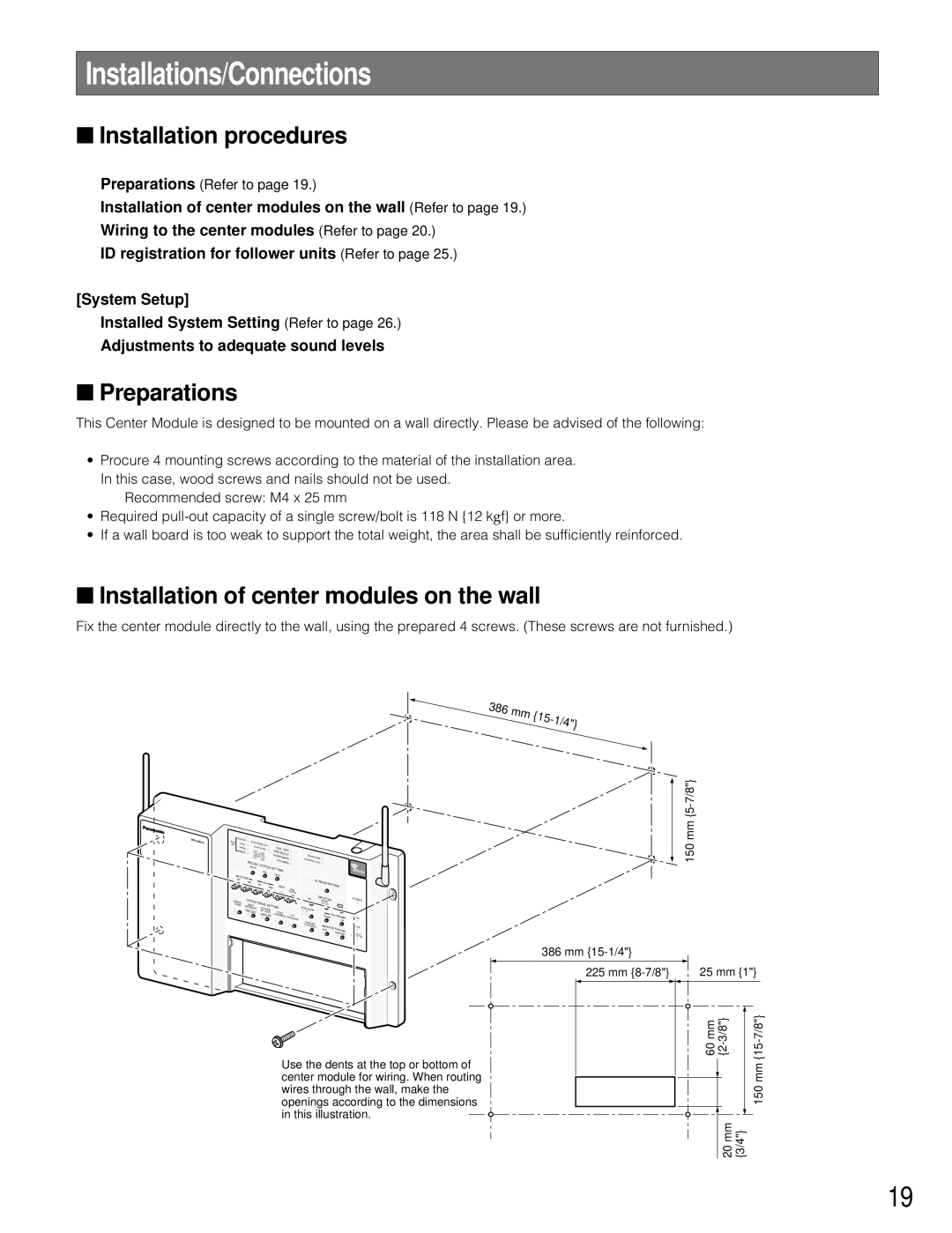
Fix the center module directly to the wall, using the prepared 4 screws. (These screws are not furnished.)
386 | mm |
|
| {15- | |
|
| 1/4"} |
AUX | AUX IN | ECHO | CANCELLER |
|
|
| |||
TALK |
|
|
| ||||||
SP |
|
|
|
| |||||
| PAGE | DNR LEVEL | DUAL LANE |
| |||||
| BEEP | RED |
| M |
| LANE | SELECT |
| |
|
| YELLOW |
| AX | POS |
| |||
|
| GREEN | MD | REMOTE |
| ||||
|
| OFF |
| LOW |
|
| |||
|
|
|
|
| OFF | TX |
| ||
|
| INSTALL | SYSTEM S | POWER |
| ||||
|
| PREV |
|
|
| ||||
|
|
|
|
|
| SEL | ETTING |
| |
| SPOUTSIDE |
|
|
|
| NEXT |
| ||
|
|
|
|
|
|
|
| ||
|
| MIC |
| SP |
| AUX |
|
|
|
|
|
|
|
| MIC |
| BEEP |
| |
|
|
|
|
|
|
| POS | ||
|
|
|
|
|
|
|
|
| |
|
|
|
|
|
|
|
|
| AUDIO |
SPEED | OPE | O |
|
|
|
| |
| RATI | NAL |
|
|
| ||
TEAM | BEEP | SETTING |
| ||||
| DAY/N | IGHT |
|
|
| ||
|
| OUTSIDE |
|
| |||
| ON:DAY | SP | LEVEL | OVV/DET |
| ||
|
|
| ON:DAY |
| |||
|
|
| ERRIDE | T/P | |||
|
|
|
|
|
|
| PRELEASE |
CTELEPHONE ONTROL OUT![]()
| ID R |
| ||
|
|
| EGISTR |
|
|
|
| ATION | |
| ON | G | REETER |
|
|
|
| START |
|
|
|
| DELAY | REC |
1 | SELECT |
|
|
|
2 |
| DOWNVOLUME | ||
|
|
| ||
| HEADSET |
|
| UP |
|
|
|
| |
| PLAYBACK |
| AUXDESTINATION | |
|
|
| ||
|
|
|
| HEADSET |
POWER | |
TALK |
|
PAGE | |
VE | E |
DETHICL |
|
ECTOR | |
150 mm
386 mm
225 mm | 25 mm {1"} |
Use the dents at the top or bottom of center module for wiring. When routing wires through the wall, make the openings according to the dimensions in this illustration.
60 mm
20 mm {3/4"}
150 mm
19
