| 37 3/8 X 2” |
|
|
| 51 | 58 | 79 |
|
| ||
| 21 |
|
|
| 51 |
|
|
FIGURE 18 | 48 |
|
|
|
|
|
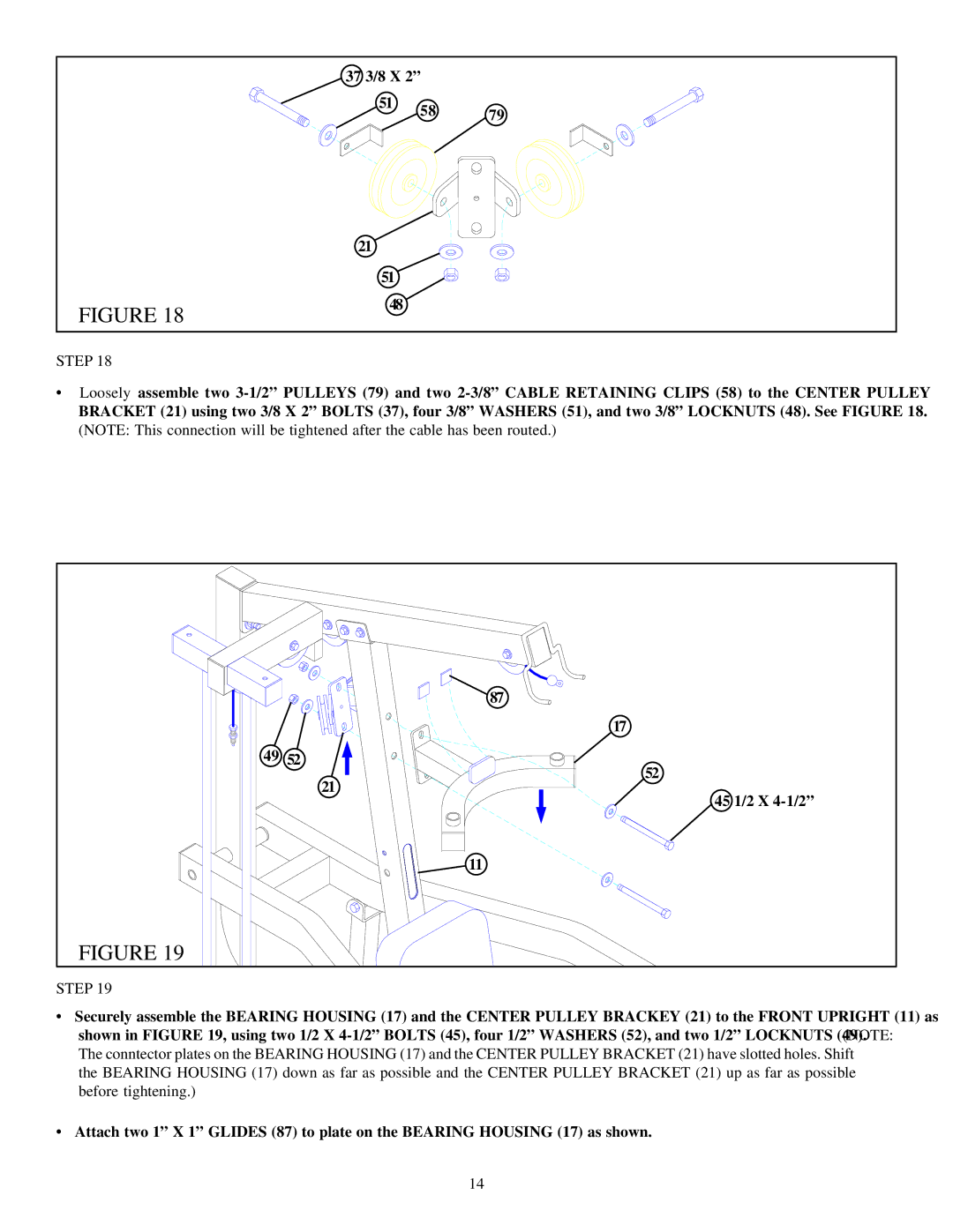
STEP 18
•Loosely assemble two
(NOTE: This connection will be tightened after the cable has been routed.)
| 87 |
| 17 |
49 | 52 |
| 52 |
| 21 |
| 45 1/2 X |
| 11 |
FIGURE 19 |
|
STEP 19
•Securely assemble the BEARING HOUSING (17) and the CENTER PULLEY BRACKEY (21) to the FRONT UPRIGHT (11) as shown in FIGURE 19, using two 1/2 X
The conntector plates on the BEARING HOUSING (17) and the CENTER PULLEY BRACKET (21) have slotted holes. Shift the BEARING HOUSING (17) down as far as possible and the CENTER PULLEY BRACKET (21) up as far as possible before tightening.)
•Attach two 1” X 1” GLIDES (87) to plate on the BEARING HOUSING (17) as shown.
14
