106 |
36 |
72 |
91 |
73 |
83 3/8 X |
105 |
75 |
104 |
1 |
70 |
71 |
34 |
106 |
FIGURE 11 |
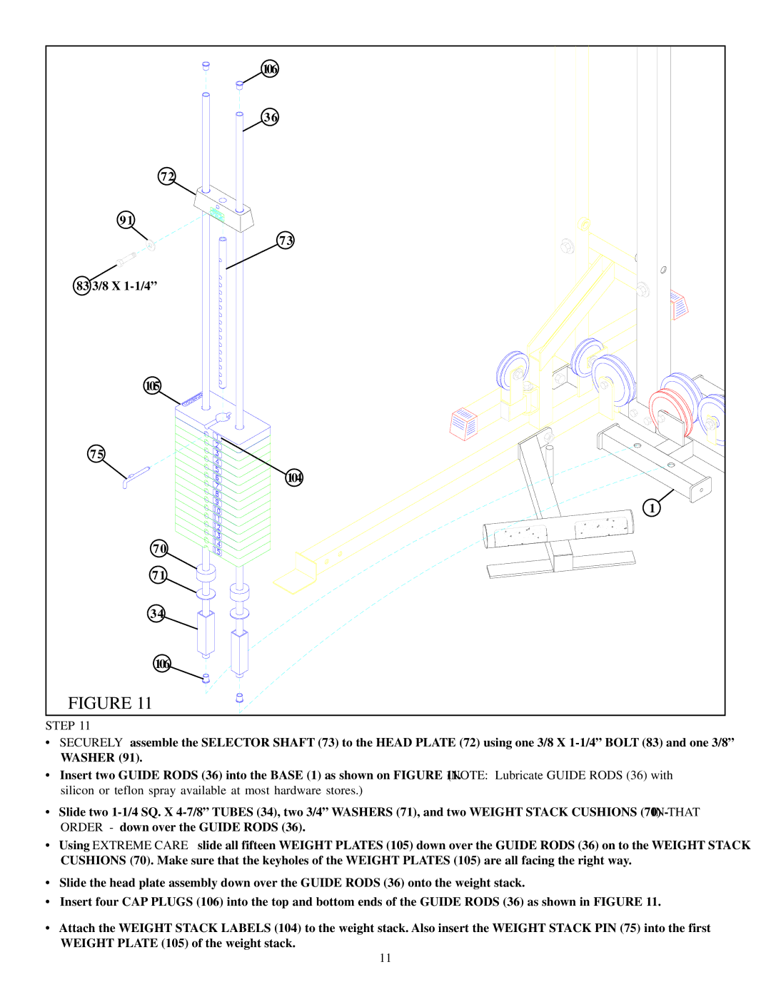
STEP 11
•SECURELY assemble the SELECTOR SHAFT (73) to the HEAD PLATE (72) using one 3/8 X
•Insert two GUIDE RODS (36) into the BASE (1) as shown on FIGURE 11. (NOTE: Lubricate GUIDE RODS (36) with silicon or teflon spray available at most hardware stores.)
•Slide two
•Using EXTREME CARE slide all fifteen WEIGHT PLATES (105) down over the GUIDE RODS (36) on to the WEIGHT STACK CUSHIONS (70). Make sure that the keyholes of the WEIGHT PLATES (105) are all facing the right way.
•Slide the head plate assembly down over the GUIDE RODS (36) onto the weight stack.
•Insert four CAP PLUGS (106) into the top and bottom ends of the GUIDE RODS (36) as shown in FIGURE 11.
•Attach the WEIGHT STACK LABELS (104) to the weight stack. Also insert the WEIGHT STACK PIN (75) into the first
WEIGHT PLATE (105) of the weight stack.
11