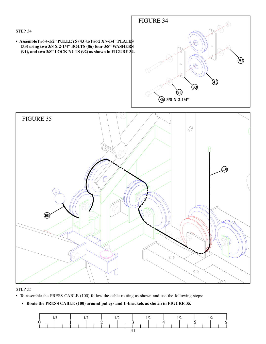
FIGURE 34
STEP 34
• Assemble two |
|
(33) using two 3/8 X |
|
(91), and two 3/8” LOCK NUTS (92) as shown in FIGURE 34. |
|
| 92 |
| 43 |
| 33 |
| 91 |
86 | 3/8 X |
FIGURE 35 |
|
| 100 |
100 |
|
STEP 35
•To assemble the PRESS CABLE (100) follow the cable routing as shown and use the following steps:
•Route the PRESS CABLE (100) around pulleys and
| 1/2 |
| 1/2 |
| 1/2 |
| 1/2 |
| 1/2 |
|
| 1/2 |
0 | 1 | 2 | 3 | 4 | 5 | 6 | ||||||
31