8 |
|
| 25 |
1/2 X 4” | 88 |
| 94 |
1 |
|
FIGURE 4 |
|
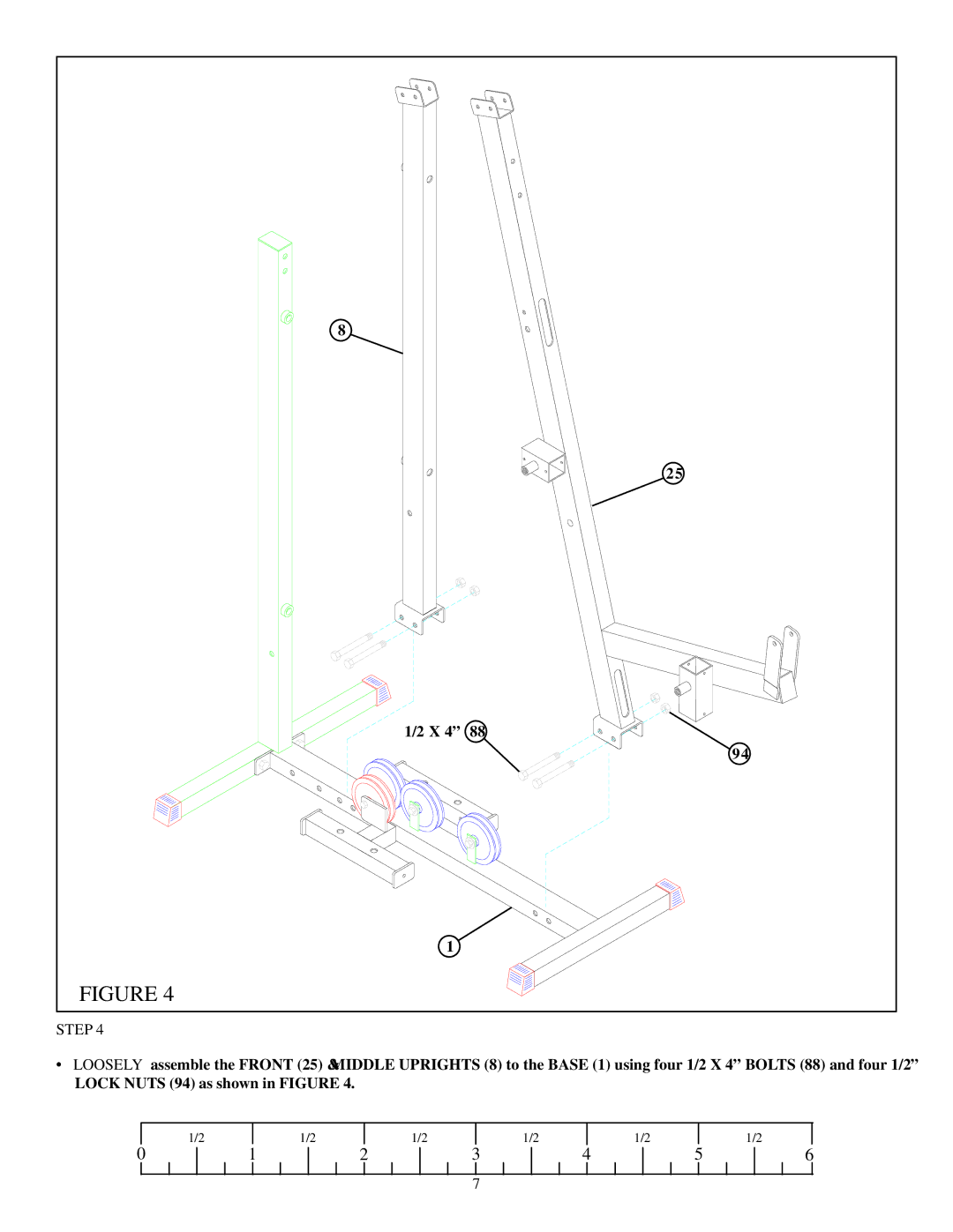
STEP 4
•LOOSELY assemble the FRONT (25) & MIDDLE UPRIGHTS (8) to the BASE (1) using four 1/2 X 4” BOLTS (88) and four 1/2” LOCK NUTS (94) as shown in FIGURE 4.
| 1/2 |
| 1/2 |
| 1/2 |
| 1/2 |
| 1/2 |
|
| 1/2 |
0 | 1 | 2 | 3 | 4 | 5 | 6 | ||||||
7
8 |
|
| 25 |
1/2 X 4” | 88 |
| 94 |
1 |
|
FIGURE 4 |
|
•LOOSELY assemble the FRONT (25) & MIDDLE UPRIGHTS (8) to the BASE (1) using four 1/2 X 4” BOLTS (88) and four 1/2” LOCK NUTS (94) as shown in FIGURE 4.
| 1/2 |
| 1/2 |
| 1/2 |
| 1/2 |
| 1/2 |
|
| 1/2 |
0 | 1 | 2 | 3 | 4 | 5 | 6 | ||||||
7