2. Cabling
Alarm Interface
The ALARM interface consists of five contacts. Three of the contacts provide access to alarm relays that that can be used to set off Major and Minor physical alarms. The other two contacts provide access to a sense circuit that can be used to detect the open or closed condition of an external alarm relay.
A
The contacts are closed during normal operation. They open in response to loss of power, hardware failure, or other alarm conditions. See ALARM Connector in Appendix A, Connectors and Pin Assignments for more information.
CAUTION:
The ALARM Sense + and Sense – contacts are intended to be connected to an external alarm relay. Do not apply power to these contacts; doing so will result in damage to the unit.
 Procedure
To connect the ALARM interface:
1.Strip the tips of the alarm source wires about 1/2 inch (13 mm).
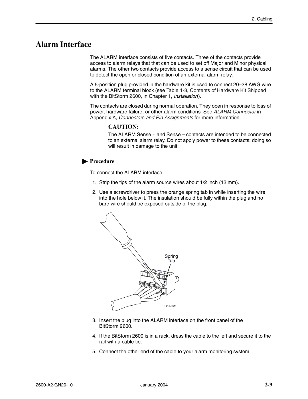
2.Use a screwdriver to press the orange spring tab in while inserting the wire into the hole below it. The insulation should be fully within the plug and no bare wire should be exposed outside of the plug.
Spring
Tab
3.Insert the plug into the ALARM interface on the front panel of the BitStorm 2600.
4.If the BitStorm 2600 is in a rack, dress the cable to the left and secure it to the rail with a cable tie.
5.Connect the other end of the cable to your alarm monitoring system.
January 2004 |