Installation
Retainer
Clips
Space |
|
|
|
|
Between |
|
| CO | |
CO Power |
|
| ||
| Power | |||
Tray and |
| |||
|
| Tray | ||
Power Module |
|
| ||
|
|
|
| |
| 3000 | DC | Power |
|
|
|
| ||
|
|
| Module | |
|
|
|
| |
SDCP
Ribbon
Cabll
Left
Power
Module
SDCP
Ribbon
Cabll
Flanges ![]()
![]()
3000 | DC | Power |
|
|
| Module | |
|
|
|
| Power |
Fan | Alarm |
|
3000 | DC | Power |
|
|
| ||
|
| Module | |
|
|
|
| Power |
Fan | Alarm |
|
Ground
Strap
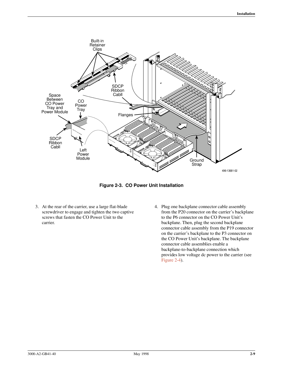
Figure 2-3. CO Power Unit Installation
3.At the rear of the carrier, use a large
4.Plug one backplane connector cable assembly from the P20 connector on the carrier's backplane to the P6 connector on the CO Power Unit's backplane. Then, plug the second backplane connector cable assembly from the P19 connector on the carrier's backplane to the P3 connector on the CO Power Unit's backplane. The backplane connector cable assemblies enable a
May 1998 |