Installation
Connecting the Alarm Contacts to a
6800 Series NMS Via a Modular 3611 DSU
The CO Power Unit can also send alarms to a
6800 Series NMS using the external alarm functions of a Modular 3611 DSU. After the CO Power Unit is installed, connect the power unit to the external leads of a Modular 3611 DSU by using an NMS adapter cable.
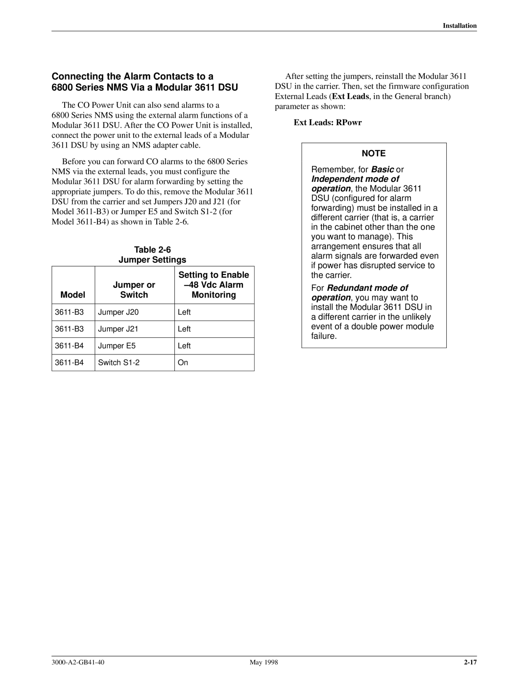
Before you can forward CO alarms to the 6800 Series NMS via the external leads, you must configure the Modular 3611 DSU for alarm forwarding by setting the appropriate jumpers. To do this, remove the Modular 3611 DSU from the carrier and set Jumpers J20 and J21 (for Model
Table
Jumper Settings
| Jumper or | Setting to Enable |
| ±48 Vdc Alarm | |
Model | Switch | Monitoring |
|
|
|
Jumper J20 | Left | |
|
|
|
Jumper J21 | Left | |
|
|
|
Jumper E5 | Left | |
|
|
|
Switch | On | |
|
|
|
After setting the jumpers, reinstall the Modular 3611 DSU in the carrier. Then, set the firmware configuration External Leads (Ext Leads, in the General branch) parameter as shown:
Ext Leads: RPowr
NOTE
Remember, for Basic or
Independent mode of operation, the Modular 3611 DSU (configured for alarm forwarding) must be installed in a different carrier (that is, a carrier in the cabinet other than the one you want to manage). This arrangement ensures that all alarm signals are forwarded even if power has disrupted service to the carrier.
For Redundant mode of operation, you may want to install the Modular 3611 DSU in a different carrier in the unlikely event of a double power module failure.
May 1998 |