Troubleshooting and Maintenance 3
Overview . . . . . . . . . . . . . . . . . . . . . . . . . . . . . . . . . . . . . . . . . . . . . . . . . . . . . . . . . . . . . . . . . . . . . . . . . .
Indicators and Controls . . . . . . . . . . . . . . . . . . . . . . . . . . . . . . . . . . . . . . . . . . . . . . . . . . . . . . . . . . . . . .
Troubleshooting . . . . . . . . . . . . . . . . . . . . . . . . . . . . . . . . . . . . . . . . . . . . . . . . . . . . . . . . . . . . . . . . . . . .
Power Module Replacement Instructions . . . . . . . . . . . . . . . . . . . . . . . . . . . . . . . . . . . . . . . . . . . . . . . . .
Preventive Maintenance . . . . . . . . . . . . . . . . . . . . . . . . . . . . . . . . . . . . . . . . . . . . . . . . . . . . . . . . . . . . . .
Overview
This chapter describes the status indicators on the power module's faceplate, provides troubleshooting guidelines and replacement instructions for the power module, and a preventive maintenance schedule for the optional air filter.
Indicators and Controls
The CO Power Unit detects power module and/or fan failures by monitoring the power output levels and the fan's
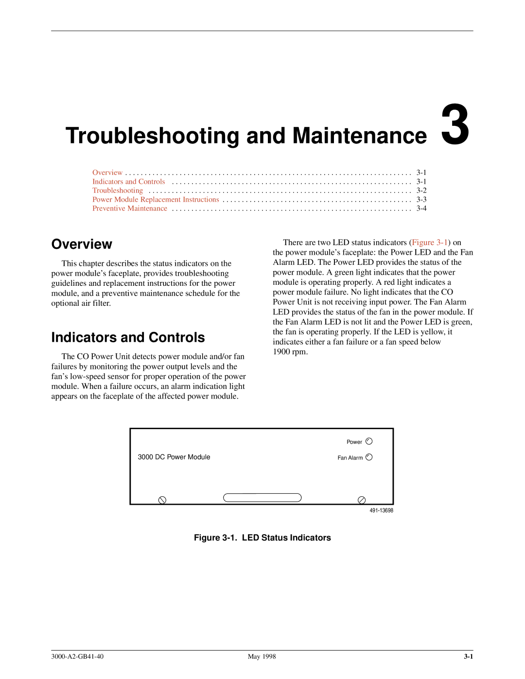
There are two LED status indicators (Figure
1900 rpm.
| Power |
3000 DC Power Module | Fan Alarm |
Figure 3-1. LED Status Indicators
May 1998 |