Installation and Startup
Connecting Camera Control Devices
There are several ways to control your camera's movement. The following information explains how to connect and configure the optional Camera Control Keypad and the SHOT Director.
Camera Control Keypad or Tracking System Keypad
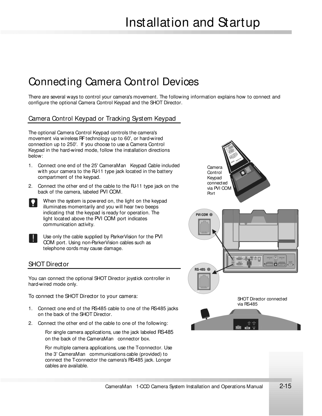
The optional Camera Control Keypad controls the camera's movement via wireless RF technology up to 60', or
1.Connect one end of the 25' CameraMan Keypad Cable included with your camera to the
2.Connect the other end of the cable to the
When the system is powered on, the light on the keypad illuminates momentarily and you will hear two beeps indicating that the keypad is ready for operation. The light located above the PVI COM port indicates communication activity.
!Use only the cable supplied by ParkerVision for the PVI COM port. Using
SHOT Director
You can connect the optional SHOT Director joystick controller in
To connect the SHOT Director to your camera:
1.Connect one end of the
2.Connect the other end of the cable to one of the following:
✦For single camera applications, use the jack labeled
✦For multiple camera applications, use the
Camera | 0FEDCB | |||
Control | ||||
| 5 | 6 | 7 | 89 |
| 4 |
|
| |
| 23 |
|
| A |
| 1 |
|
| |
Keypad ![]()
![]()
![]()
![]()
![]()
![]()
![]()
![]()
![]()
![]()
![]()
![]() connected
connected ![]() via PVI COM
via PVI COM ![]()
Port
| ||
SWITCH BANK |
| SWITCH BANK |
| ||
| COMPOSITE | |
1 | 2 | 3 | 4 | 5 | 6 | 7 | 8 | BASE UNIT | 1 | 2 | 3 | 4 | 5 | 6 | 7 | 8 | TALLY LIGHT |
|
|
|
|
|
|
|
| ADDRESS |
|
|
|
|
|
|
|
| INTERFA CE |
UP |
|
|
|
|
|
|
|
|
|
|
|
|
|
|
|
|
|
D OW N |
|
|
|
|
|
|
|
|
|
|
|
|
|
|
|
|
|
SHOT Director connected via
LCD | LCD |
CONTRAST | BRIGHT NESS |
COM 1
|
|
|
|
|
|
|
|
|
|
|
|
|
|
|
|
|
|
|
|
|
|
|
|
|
|
|
|
|
|
|
|
|
|
|
|
|
|
|
|
|
|
|
|
|
|
|
|
|
|
|
|
|
|
|
|
|
|
|
|
|
|
|
|
|
|
|
|
|
|
|
|
|
|
|
|
|
|
|
|
|
|
|
|
|
|
|
|
|
|
|
|
|
|
|
|
|
|
|
|
|
|
|
|
|
|
|
|
|
|
|
|
|
|
|
|
|
|
|
|
|
|
|
|
|
|
|
|
|
|
|
|
CameraMan |
| ||||||||||||||||||||
|
|
| |||||||||||||||||||
|
|
|
|
|
|
|
|
|
|
|
|
|
|
|
|
|
|
|
|
|
|
|
|
|
|
|
|
|
|
|
|
|
|
|
|
|
|
|
|
|
|
|
|
|
|
|
|
|
|
|
|
|
|
|
|
|
|
|
|
|
|
|
|
|
|
|
|
|
|
|
|
|
|
|
|
|
|
|
|
|
|
|
|
|
|
|
|
|
|
|
|
|
|
|
|
|
|
|
|
|
|
|
|
|
|
|
|
|
|
|
|
|
|
|
|
|
|
|
|
|
|
|
|
|
|
|
|
|
|
|
|
|
|
|
|
|
|
|
|
|
|
|
|
|
|
|
|
|
|
|
|
|
|
|
|
|
|
|
|
|
|
|
|
|
|
|
|
|
|
|
|
|
|
|
|
|
|
|
|
|
|
|
|
|
|
|
|
|
|
|
|
|
|
|
|
|
|
|
|
|
|
|
|
|
|
|
|
|
|
|
|
|
|
|
|
|
|
|
|
|
|
|
|
|
|
|
|
|
|
|
|
|
|
|
|
|
|
|
|
|
|
|
|
|
|
|
|
|
|
|
|
|
|
|
|
|
|
|
|
|
|
|
|