Installation and Startup
Configuration Table
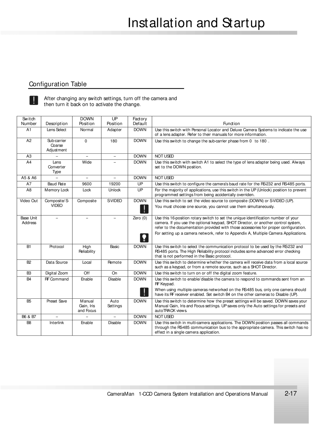
!After changing any switch settings, turn off the camera and then turn it back on to activate the change.
| Switch |
|
|
|
| DOWN |
| UP |
| Factory |
|
|
|
|
|
|
|
|
|
|
|
|
|
|
|
|
|
|
| |||||
| Number | Description | Position | Position |
| Default |
|
|
|
|
|
|
|
|
| Function |
| |||||||||||||||||
|
|
|
|
|
|
|
|
|
|
| ||||||||||||||||||||||||
| A1 |
| Lens Select | Normal | Adapter |
| DOWN |
| Use this switch with Personal Locator and Deluxe Camera Systems to indicate the use |
| ||||||||||||||||||||||||
|
|
|
|
|
|
|
|
|
|
|
|
|
|
|
|
| of a lens adapter. Refer to their manuals for more information. |
| ||||||||||||||||
|
|
|
|
|
|
|
|
|
|
|
|
| ||||||||||||||||||||||
| A2 |
| 0° |
| 180° |
|
| DOWN |
| Use this switch to change the |
| |||||||||||||||||||||||
|
|
|
| Coarse |
|
|
|
|
|
|
|
|
|
|
|
|
|
|
|
|
|
|
|
|
|
|
|
|
|
|
|
| ||
|
|
| Adjustment |
|
|
|
|
|
|
|
|
|
|
|
|
|
|
|
|
|
|
|
|
|
|
|
|
|
|
|
| |||
|
|
|
|
|
|
|
|
|
|
|
|
| ||||||||||||||||||||||
| A3 |
|
|
|
| DOWN |
| NOT USED |
| |||||||||||||||||||||||||
|
|
|
|
|
|
|
|
|
|
|
| |||||||||||||||||||||||
| A4 |
| Lens | Wide |
|
| DOWN |
| Use this switch with switch A1 to select the type of lens adapter being used. Always |
| ||||||||||||||||||||||||
|
|
|
| Converter |
|
|
|
|
|
|
|
|
|
| set to the DOWN position. |
| ||||||||||||||||||
|
|
|
| Type |
|
|
|
|
|
|
|
|
|
|
|
|
|
|
|
|
|
|
|
|
|
|
|
|
|
|
|
| ||
|
|
|
|
|
|
|
|
|
|
|
|
| ||||||||||||||||||||||
| A5 & A6 |
|
|
|
| DOWN |
| NOT USED |
| |||||||||||||||||||||||||
|
|
|
|
|
|
|
|
|
|
|
|
| ||||||||||||||||||||||
| A7 |
| Baud Rate | 9600 |
| 19200 |
|
| UP |
| Use this switch to configure the camera's baud rate for the |
| ||||||||||||||||||||||
|
|
|
|
|
|
|
|
|
| |||||||||||||||||||||||||
| A8 | Memory Lock | Lock | Unlock |
| UP |
| For the majority of applications, use this switch in the UP (Unlock) position to prevent |
| |||||||||||||||||||||||||
|
|
|
|
|
|
|
|
|
|
|
|
|
|
|
|
| programmed settings from being accidentally overriden. |
| ||||||||||||||||
|
|
|
|
|
|
|
|
|
| |||||||||||||||||||||||||
| Video Out | Composite/S- | Composite |
| DOWN |
| Use this switch to set the video source to composite (DOWN) or |
| ||||||||||||||||||||||||||
|
|
|
| VIDEO |
|
|
|
|
|
|
| ! |
| You must choose one source, you cannot use them simultaneously. |
| |||||||||||||||||||
|
|
|
|
|
|
|
|
|
|
|
|
|
|
| ||||||||||||||||||||
|
|
|
|
|
|
|
|
|
|
|
|
| ||||||||||||||||||||||
| Base Unit |
|
|
|
| Zero (0) |
| Use this |
| |||||||||||||||||||||||||
| Address |
|
|
|
|
|
|
|
|
|
|
|
|
|
| camera. If you use the optional keypad, SHOT Director, or another control system, |
| |||||||||||||||||
|
|
|
|
|
|
|
|
|
|
|
|
|
|
|
|
| refer to the documentation provided with those accessories for proper configuration. |
| ||||||||||||||||
|
|
|
|
|
|
|
|
|
|
|
|
|
|
|
|
| For setting up a camera network, refer to Appendix A, Multiple Camera Applications. |
| ||||||||||||||||
|
|
|
|
|
|
|
|
|
|
| ||||||||||||||||||||||||
| B1 |
| Protocol | High | Basic |
| DOWN |
| Use this switch to select the communication protocol to be used by the |
| ||||||||||||||||||||||||
|
|
|
|
|
|
| Reliability |
|
|
|
|
|
|
|
| |||||||||||||||||||
|
|
|
|
|
|
|
|
|
|
|
|
|
|
|
|
| that is not performed in the Basic protocol. |
| ||||||||||||||||
|
|
|
|
|
|
|
|
|
| |||||||||||||||||||||||||
| B2 | Data Source | Local | Remote |
| DOWN |
| Use this switch to determine whether the camera will receive data from a local source |
| |||||||||||||||||||||||||
|
|
|
|
|
|
|
|
|
|
|
|
|
|
|
|
| such as a keypad, or from a remote source, such as a SHOT Director. |
| ||||||||||||||||
|
|
|
|
|
|
|
|
|
|
|
| |||||||||||||||||||||||
| B3 | Digital Zoom |
| Off |
| On |
| DOWN |
| Use this switch to turn on or off the digital zoom feature. |
| |||||||||||||||||||||||
|
|
|
|
|
|
|
|
|
| |||||||||||||||||||||||||
| B4 | RF Command | Enable | Disable |
| DOWN |
| Use this switch to enable/disable the camera to respond to commands sent from an |
| |||||||||||||||||||||||||
|
|
|
|
|
|
|
|
|
|
|
|
|
| ! |
| RF Keypad. |
| |||||||||||||||||
|
|
|
|
|
|
|
|
|
|
|
|
|
|
| When using multiple cameras networked on the |
| ||||||||||||||||||
|
|
|
|
|
|
|
|
|
|
|
|
|
|
| have its RF receiver enabled. Set switch B4 on the other cameras to Disable (UP). |
| ||||||||||||||||||
| B5 |
| Preset Save | Manual | Auto |
| DOWN |
| Use this switch to determine how the preset settings will be saved. DOWN saves your |
| ||||||||||||||||||||||||
|
|
|
|
|
|
| Gain, Iris | Settings |
|
|
|
| Manual Gain, Iris and Focus settings. UP saves only the Auto settings for presets and |
| ||||||||||||||||||||
|
|
|
|
|
|
| and Focus |
|
|
|
|
|
|
| autoTRACK views. |
| ||||||||||||||||||
|
|
|
|
|
|
|
|
|
|
|
|
| ||||||||||||||||||||||
| B6 & B7 |
|
|
|
| DOWN |
| NOT USED |
| |||||||||||||||||||||||||
|
|
|
|
|
|
|
|
|
|
| ||||||||||||||||||||||||
| B8 |
| Interlink | Enable | Disable |
| DOWN |
| Use this switch in |
| ||||||||||||||||||||||||
|
|
|
|
|
|
|
|
|
|
|
|
|
|
|
|
| through the |
| ||||||||||||||||
|
|
|
|
|
|
|
|
|
|
|
|
|
|
|
|
| effect in a single camera application. |
| ||||||||||||||||
|
|
|
|
|
|
|
|
|
|
|
|
|
|
|
|
|
|
|
|
|
|
|
|
|
|
|
|
|
|
|
|
|
|
|
|
|
|
|
|
|
|
|
|
|
|
|
|
|
|
|
|
|
|
|
|
|
|
|
|
|
|
|
|
|
|
|
|
|
|
|
|
|
|
|
|
|
|
|
|
|
|
|
|
|
|
|
|
|
|
|
|
|
|
|
|
|
|
|
|
|
|
|
|
|
|
|
|
|
|
|
|
|
|
|
|
|
|
|
|
|
|
|
|
|
|
|
|
|
|
|
|
|
|
|
|
|
|
|
|
|
|
|
|
|
|
|
|
|
|
|
|
|
|
|
|
|
|
|
|
|
|
|
|
|
|
|
|
|
|
|
|
|
|
|
|
|
|
|
|
|
|
|
|
|
|
|
|
|
|
|
|
|
|
|
|
|
|
|
|
|
|
|
|
|
|
|
|
|
|
|
|
|
|
|
|
|
|
|
|
|
|
|
|
|
|
|
|
|
|
|
|
|
|
|
|
|
|
|
|
|
|
|
|
|
|
|
|
|
|
|
|
|
|
|
|
|
|
|
|
|
|
|
|
|
|
|
|
|
|
|
|
|
|
|
|
|
|
|
|
|
|
|
|
|
|
|
|
|
|
|
|
|
|
|
|
|
|
|
|
|
|
|
|
|
|
|
|
|
|
|
|
|
|
|
|
|
|
|
|
|
|
|
|
|
|
|
|
|
|
|
|
|
|
|
|
|
|
|
|
|
|
|
|
|
|
|
|
|
|
|
|
|
|
|
|
|
|
|
|
|
|
|
|
|
|
|
|
|
|
|
|
|
|
|
|
|
|
|
|
|
|
|
|
|
|
|
|
|
|
|
|
|
|
|
|
|
|
|
|
|
|
|
|
|
|
|
|
|
|
|
|
|
|
|
|
|
|
|
|
|
|
|
|
|
|
|
|
|
|
|
|
|
|
|
|
|
|
|
|
|
|
|
|
|
|
|
|
|
|
|
|
|
|
|
|
|
|
|
|
|
|
|
|
|
|
|
|
|
|
|
|
|
|
|
|
|
|
|
|
|
|
|
|
|
|
|
|
|
|
|
|
|
|
|
|
|
|
|
|
|
|
|
|
|
|
|
|
|
|
|
|
|
|
|
|
|
|
|
|
|
|
|
|
|
CameraMan | |
| |
|
|
|
|
|
|
|
|
|
|
|
|
|
|
|
|
|
|
|
|
|
|
|
|