Section
3 Appendices
A: Multiple Camera Applications
If your application requires that you have more than one CameraMan , you will need to set them up in a
Daisy-chain Network Configuration
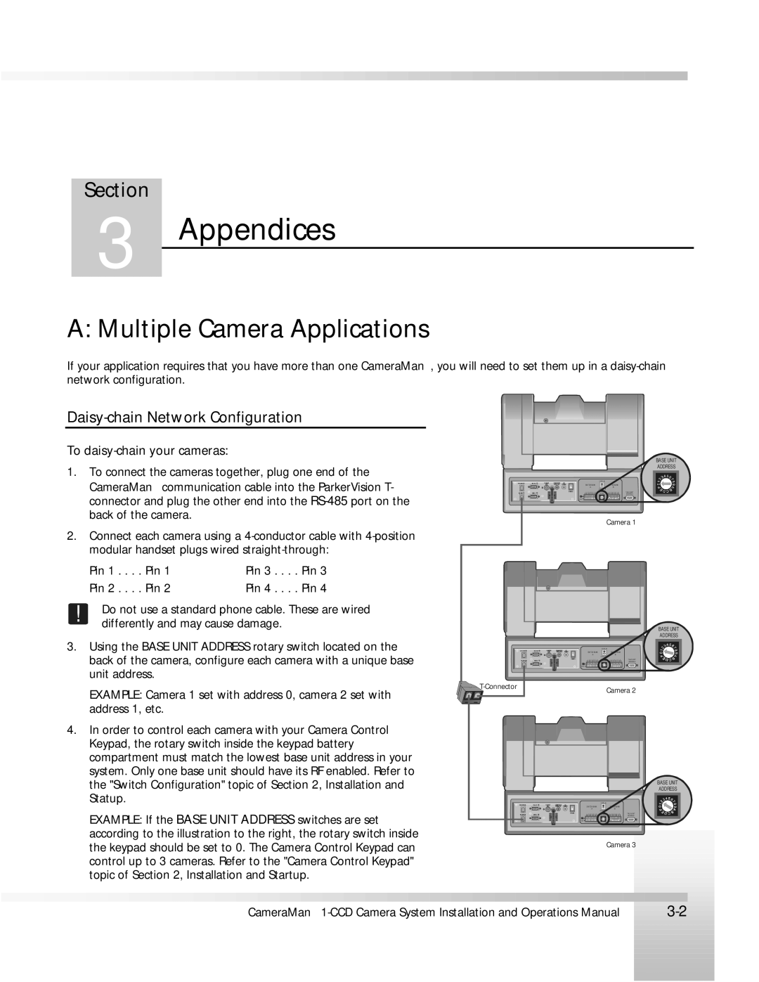
To daisy-chain your cameras:
1.To connect the cameras together, plug one end of the CameraMan communication cable into the ParkerVision T- connector and plug the other end into the
BASE UNIT
ADDRESS
SWITCH BA NK | TCH BA NK |
1 | 2 | 3 | 4 | 5 | 6 | 7 | 8 | 1 | 2 | 3 | 4 | 5 | 6 | 7 | 8 | TALLY LIGHT |
|
|
|
|
|
|
|
|
|
|
|
|
|
|
|
| INTERFACE |
Camera 1
2.Connect each camera using a
Pin 1 . . . . | Pin 1 | Pin 3 . . . . | Pin 3 |
Pin 2 . . . . | Pin 2 | Pin 4 . . . . | Pin 4 |
! | Do not use a standard phone cable. These are wired |
differently and may cause damage. | |
3. Using the BASE UNIT ADDRESS rotary switch located on the | |
| back of the camera, configure each camera with a unique base |
| unit address. |
| EXAMPLE: Camera 1 set with address 0, camera 2 set with |
| address 1, etc. |
4. In order to control each camera with your Camera Control | |
| Keypad, the rotary switch inside the keypad battery |
| compartment must match the lowest base unit address in your |
| system. Only one base unit should have its RF enabled. Refer to |
![]()
BASE UNIT
ADDRESS
SWITCH BA NK |
|
|
|
| BA NK |
| |||
|
|
|
|
|
|
|
| ||
1 2 3 | 4 5 | 6 | 7 8 | 1 | 2 | 3 | 4 5 | 6 7 8 | TALLY LIGHT |
|
|
|
|
|
|
|
|
| INTERFACE |
Camera 2
the "Switch Configuration" topic of Section 2, Installation and |
Statup. |
EXAMPLE: If the BASE UNIT ADDRESS switches are set |
according to the illustration to the right, the rotary switch inside |
the keypad should be set to 0. The Camera Control Keypad can |
control up to 3 cameras. Refer to the "Camera Control Keypad" |
topic of Section 2, Installation and Startup. |
BASE UNIT
ADDRESS
SWITCH BA NK |
|
|
|
| BA NK |
| |||||
|
|
|
|
|
|
|
|
|
| ||
1 | 2 | 3 | 4 5 | 6 | 7 8 | 1 | 2 | 3 | 4 5 | 6 7 8 | TALLY LIGHT |
|
|
|
|
|
|
|
|
|
|
| INTERFACE |
Camera 3
|
|
|
|
|
|
|
|
|
|
|
|
|
|
|
|
|
|
|
|
|
|
|
|
|
|
|
|
|
|
|
|
|
|
|
|
|
|
|
|
|
|
|
|
|
|
|
|
|
|
|
|
|
|
|
|
|
|
|
|
|
|
|
|
|
|
CameraMan |
| ||||||||||||||||||||
|
|
| |||||||||||||||||||
|
|
|
|
|
|
|
|
|
|
|
|
|
|
|
|
|
|
|
|
|
|
|
|
|
|
|
|
|
|
|
|
|
|
|
|
|
|
|
|
|
|
|
|
|
|
|
|
|
|
|
|
|
|
|
|
|
|
|
|
|
|
|
|
|
|
|
|
|
|
|
|
|
|
|
|
|
|
|
|
|
|
|
|
|
|
|
|
|
|
|
|
|
|
|
|
|
|
|
|
|
|
|
|
|
|
|
|
|
|
|
|
|
|
|
|
|
|
|
|
|
|
|
|
|
|
|
|
|
|
|
|
|
|
|
|
|
|
|
|
|
|
|
|
|
|
|
|
|
|
|
|
|
|
|
|
|
|
|
|
|
|
|
|
|
|
|
|
|
|
|
|
|
|
|
|
|
|
|
|
|
|
|
|
|
|
|
|
|
|
|
|
|
|
|
|
|
|
|
|
|
|
|
|
|
|
|
|
|
|
|
|
|
|
|
|
|
|
|
|
|
|
|
|
|
|
|
|
|
|
|
|
|
|
|
|
|
|
|
|
|
|
|
|
|
|
|
|
|
|
|
|
|
|
|
|
|
|
|
|
|
|
|
|