5.0 OPERATION
Once the VLINK modems are properly installed, they should operate transparently. No user settings required. This section describes reading the LED status monitors.
5.1 POWER UP
Before applying power to the VLINK modem, please review section 3.6, “Connecting Power” on page 12 to verify that the unit is connected to the
appropriate power source.
There are no
WARNING
5.2 FRONT PANEL LED STATUS MONITORS
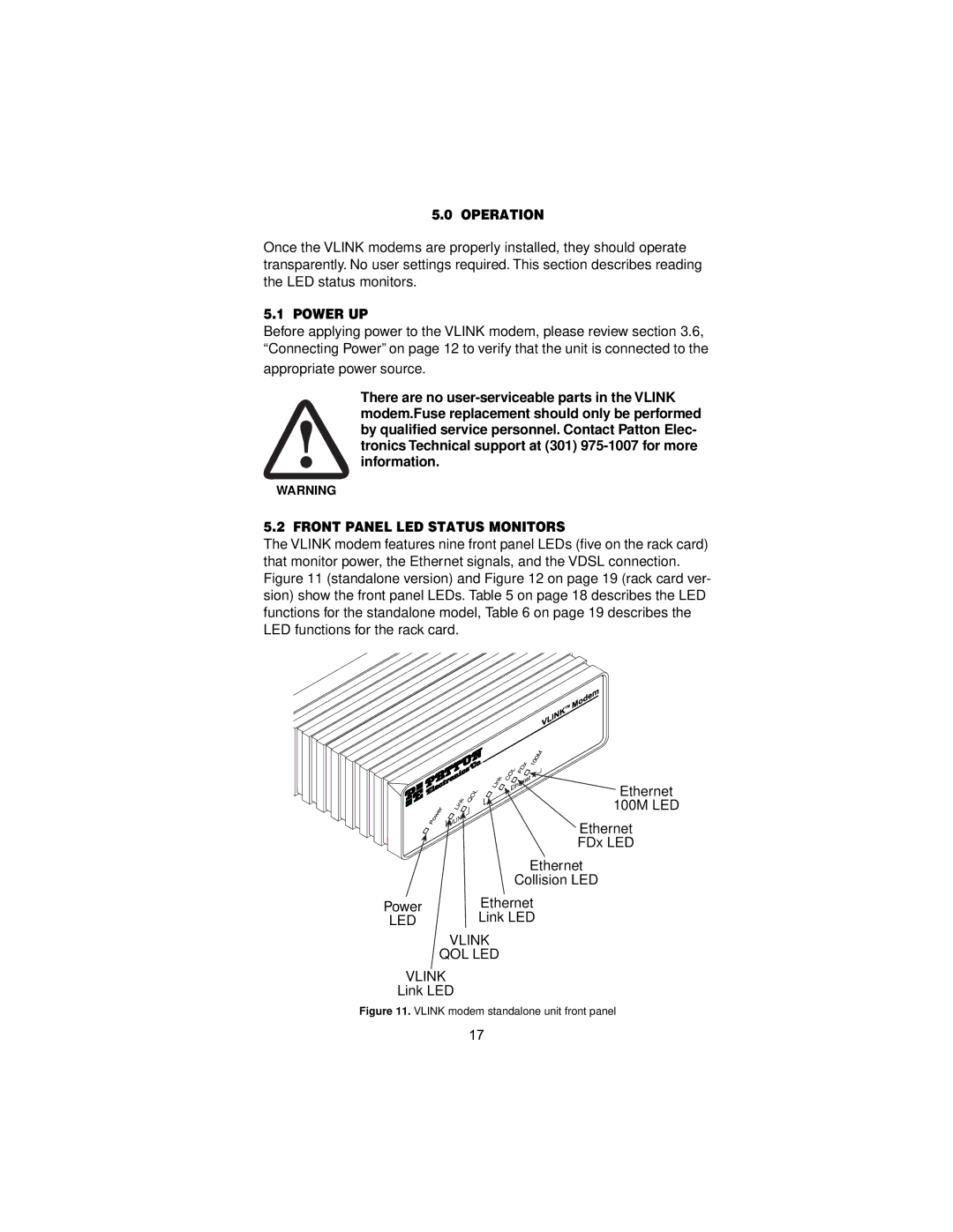
The VLINK modem features nine front panel LEDs (five on the rack card) that monitor power, the Ethernet signals, and the VDSL connection. Figure 11 (standalone version) and Figure 12 on page 19 (rack card ver- sion) show the front panel LEDs. Table 5 on page 18 describes the LED functions for the standalone model, Table 6 on page 19 describes the LED functions for the rack card.
| Ethernet |
| 100M LED |
| Ethernet |
| FDx LED |
| Ethernet |
| Collision LED |
Power | Ethernet |
LED | Link LED |
| VLINK |
| QOL LED |
VLINK
Link LED
Figure 11. VLINK modem standalone unit front panel
17